700-SDI-RADAR-300W-Man Rev 2 30 May 2022
36
/39
Part# 21370
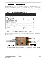
Table A-1: Pin Description
Pin No. Pin Name Pin Description
Connect To
Left 4
RS485 – D+ RS-485 to radar
Dark red wire (D+) on radar cable
Left 5
RS485 – D- RS-485 to radar
Orange wire (D-) on radar cable
Left 7
Power
Output
Power output to radar
Brown wire (+Vin) on radar cable
Left 8
GND
Power ground to radar
White wire (GND) on radar cable
Right 1
SDI-12
SDI-12 data to data logger
SDI-12 datalogger data line
Right 5
PWR1 IN
Power supply input 9 VDC
to 27 VDC
Main power supply V+
Right 6
GND
Power ground
Main power supply GND
Figure A-2: SDI-12 Adapter to radar wiring Figure A-3: SDI-12 Adapter to data logger wiring
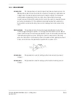
After all wires are connected and power supply is connected to input, the SDI12 adapter is in initial
mode. Its status is indicated by the COM LED.
COM LED
MEANING
Constantly ON
The adapter is communicating with (or attempting to communicate with)
a device on the RS-232 input
OFF
After 10 seconds of initial mode, the LED turns off and the adapter
reverts to constant operational mode.

