background image


700-SDI-RADAR-300W-Man  Rev 2   30 May 2022 

2

/39 

Part# 21370 


PRODUCT DESCRIPTION 

2.1


FUNCTIONAL PRINCIPLE 

The SDI-RADAR-300W

 flow meter

, referred to as the 300W in this manual,

 uses radar technology to 

provide precise contactless measurement of surface flow velocity. Contactless radar technology 

enables quick and simple sensor installation above the water surface and requires minimum 

maintenance. This functionality is achieved by transmitting an electromagnetic wave in the 24 

GHz frequency range (K-band) and measuring the frequency shift of the electromagnetic wave 

reflected from the flowing water surface. The frequency shift is caused by the Doppler effect of 

the moving surface on the electromagnetic wave. As the relative speed between the radar 

sensor and the water surface increases, the detected frequency shift also increases, thus 

enabling the flow meter to precisely determine the surface flow velocity. 


The 300W reports the average surface velocity of the area covered by its beam and uses 

complex Kalman filters with physical modelling of the water flow to give stable measurements 

even under turbulent conditions. However, moderate waviness of the water surface will 

improve the measurement (see Section 3.4). In strongly turbulent water flow, fluctuations in 

measured data could be expected as well as somewhat reduced measurement accuracy. If 

strongly turbulent flow can be expected at monitoring site, then the filter length of the radar 

should be configured to 120 or more. 


The flow meter is able to detect water flow traveling at speeds ranging from 0.02 m/s to 15.0 
m/s with precision of 0.01 m/s

1

.  The integrated tilt sensor measures the inclination angle of 

the sensor and the flow velocity measurement is automatically cosine-corrected according to 

the measured mounting tilt angle. 


2.2


INTERFERENCE AND MULTIPLE RADARS 

The 300W operates in K band, in frequency range around 24.125 GHz. Frequency stability and phase 
noise of the internal oscillator is very good and always trimmed in factory to a precise central 
frequency making the likelihood of two devices working on the exact same frequency to cause 
interference highly unlikely.  The Doppler frequency shift caused by water in the speed range up to 
15 m/s is measured in kHz frequency shift.  As this frequency shift is relatively small in comparison 
to the central frequency, in most cases below 0.00005%, it will be required to keep the difference 
between central frequencies of two radars in the same range to get interference. 

Similarly, is very unlikely that other radiation sources in the K band in the vicinity will affect the 300W 
measurements. Some wideband radiation sources can introduce small impulse interference for a 
short period of time, but this is very unlikely to affect measurements reported by the radar.  


1


0.04 mph to 33.55 mph with a precision of 0.02 mph 


Summary of Contents for 21370

Page 1: ...EXTREME ENVIRONMENTS EXTREMELY RELIABLE SDI RADAR 300W Surface Flow Velocity Radar Operating Manual 1 800 548 4264 www ftsinc com 700 SDI RADAR 300W Man Rev 2 30 May 2022 Part 21370...

Page 2: ...ormation Canadian Headquarters 1065 Henry Eng Place Victoria BC V9B 6B2 Canada www ftsinc com Toll free 1 800 548 4264 Local 250 478 5561 Technical support portal http support ftsinc com Email service...

Page 3: ...NG AND EVAPORATION 6 3 4 REFLECTIONS 7 4 1 SERIAL INTERFACES 8 4 1 1 SERIAL RS 232 INTERFACE 8 4 1 2 SERIAL RS 485 INTERFACE 8 4 2 DATA PROTOCOLS 8 4 2 1 NMEA PROTOCOL RS 232 9 4 2 2 SERVICING PROTOCO...

Page 4: ...ii A 1 ELECTRICAL CHARACTERISTICS 35 A 2 CONNECTING TO THE SDI RADAR 300W 35 A 3 TROUBLESHOOTING SDI 12 ADAPTER ERRORS 37...

Page 5: ...g regulations and guidelines During the entire duration of use the user is obliged to determine the compliance of the necessary occupational safety measures with the current valid rules and regulation...

Page 6: ...educed measurement accuracy If strongly turbulent flow can be expected at monitoring site then the filter length of the radar should be configured to 120 or more The flow meter is able to detect water...

Page 7: ...ply 2 Brown Vin Power supply Power supply voltage must be 9 to 22 VDC and the power supply must be able to provide at least 0 65W 3 Green RS232 TxD RS 232 data transmit signal RS232 connections only u...

Page 8: ...dB Azimuth Beamwidth 3dB Elevation 24 75 108 24 125 110 12 24 24 175 20 112 GHz dBm dBm degrees degrees Power supply voltage 9 0 12 0 27 0 V Power Operational Mode Sleep Mode 950 85 mW mW Alarm output...

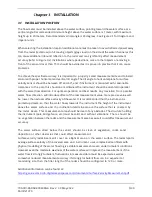
Page 9: ...l water flow direction will introduce offset of the real measurement value more precise value will be lower than actual surface velocity of the water It is recommended that the instrument is pointed u...

Page 10: ...nt To further improve rain filtering the radar should be configured to report only incoming direction of water flow In this case the radar will completely ignore all movement with direction going away...

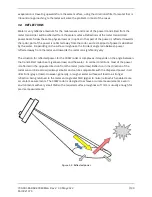
Page 11: ...angle ratio between power reflected away from the radar and towards the radar can significantly vary The situation for reflected power for the 300W radar is complex as it depends on the angle between...

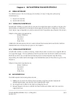
Page 12: ...terface Detailed description of the protocol is given in the Chapter 4 4 1 2 SERIAL RS 485 INTERFACE Serial RS 485 interface is used for connecting multiple flow meters connected on a single RS 485 bu...

Page 13: ...nal reflection from the water surface CSUM The check sum of the characters in the report from to excluding these characters Average flow measurement report RDAVG S1 CSUM CR LF RDAVG The keyword sent o...

Page 14: ...hanges the sensitivity of the radar sensor set_thld 0 100 Change detected targets direction Changes the parameter that specifies which flow direction will be reported set_direction in set_direction ou...

Page 15: ...interface which allows the connection of multiple units on a single RS 485 line Before the units are connected on the single RS 485 bus each unit must be configured with a different device identifier...

Page 16: ...CSUM Checksum calculated by adding in modulo 256 the two byte values of the ID and All byte values from the SPEED 4 2 4 MODBUS PROTOCOL RS 485 When configured in Modbus operation mode the unit respond...

Page 17: ...nt Data CRC16 Length 1 byte 1 byte 1 byte 2 bytes H L 2 bytes L H Example 0X01 0X03 0X02 0X00 0X01 0X79 0X84 Table 4 4 Response Example Name Content Detail Address 0X01 Slave address Sensor ID Functio...

Page 18: ...tion 0X0009 2 bytes 0 both 1 incoming 2 outgoing Read flow direction filter setting 0000A 2 bytes 0 100 Read sensitivity value 0X000B 2 bytes 0 2048 Read relative signal strength 0X000C 2 bytes 0 Norm...

Page 19: ...es 0 128 Read number of predefined points that define channel geometry 0X0019 2 bytes 0 128 Read number of k coeff values 0X001A 0X0099 128 2 byte From 32768 To 32 767 Relative height in cm for each p...

Page 20: ...2 bytes 0 ASCII64 1 NMEA 2 ASCIIV 3 AVIO 4 SDI12 Change RS 232 protocol type 0X0009 2 bytes 0 HS 1 MODBUS RTU Change RS 485 protocol type 0000A 2 bytes 0 8 Change PGA sensitivity 0X000B 2 bytes 0 Dis...

Page 21: ...e message for commands with CRC The measurement command must be followed by a Send Data command aD0 to view the data Name Command Response and Details Address Query a Device responds with its SDI 12 a...

Page 22: ...will be negative if the water is flowing away from the sensor face Water flow towards sensor Water flow away from sensor positive velocity readings negative velocity readings X COMMANDS In addition t...

Page 23: ...m s 3 km h Read Unit Type Read last value aXGRHR 2 then aXGRMV Response a val0 val0 number of seconds to wait until the holding register is available for reading Input Read last value command after wa...

Page 24: ...be calculated as d1 10 1 For example if d1 is 20 then d2 is 3 if d1 is 35 then d2 should be 4 Read Data Filter Length Read last value aXGRHR 7 then aXGRMV Response a val0 val0 number of seconds to wai...

Page 25: ...rmine the Modbus address of the desired data IMPORTANT In the following commands the register address denoted by d or d1 must be replaced with a numeric value not the hexadecimal value listed in the D...

Page 26: ...r Address Numeric Value 0X0000 0 0000A 10 0X0014 20 0X0001 1 0X000B 11 0X0015 21 0X0002 2 0X000C 12 0X0016 22 0X0003 3 0X000D 13 0X0017 23 0X0004 4 0X000E 14 0X0018 24 0X0005 5 0X000F 15 0X0019 25 0X0...

Page 27: ...y displays its main window Initially no flow data is displayed as the connection to the flow meter device is not established 5 1 CONNECTING THE RADAR TO THE CONFIGURATOR 1 Connect the RS 232 serial ca...

Page 28: ...ata link is established active device parameters will be displayed and the flow velocity measurements will be displayed 1 Connect the green wire RS232 TxD from the radar to the green wired terminal cl...

Page 29: ...GS 5 2 1 INTERFACES Baud Ratel Configures the setting controls how many bits are sent on the communication line in one second The available values are standardized Using higher baud rate over longer l...

Page 30: ...nterface HS protocol is a simple request response protocol for the simplest applications Modbus RTU protocol is a standardized protocol which is commonly used in automation and instrumentation as it p...

Page 31: ...bus is even parity Stop bits are added to the end of each data byte transferred over serial communication to allow pause between two bytes The default setting is even parity and one stop bit Warm Up T...

Page 32: ...to the instrument minimum of 0 mm s 4 20 mA max To configure the 4 20 mA output range the maximum measured value which will correspond to 20 mA analog output needs to be set The value is set in the c...

Page 33: ...s with SNR below 6 dB should not be trusted The SNR threshold should be set accordingly Filter Length The length of the averaging filter in number of readings to smoothen the measured values The instr...

Page 34: ...nt will reject all radar returns that correspond to outgoing flow and vice versa On monitoring sites where it is expected that the flow will always be in only one direction it is recommended to proper...

Page 35: ...actor which is used over RS 232 protocol and it displays the correct values to the user PGA Sensitivity This parameter limits the maximum gain amplification level of the internal programable gain ampl...

Page 36: ...by multiplying mean flow velocity and the channel cross section area The cross section area is the area of the slice in the water column made perpendicular to the flow direction For an ideal case let...

Page 37: ...nt The mean cross section flow velocity needs to be determined from measured surface flow velocity Studies performed by USGS reveal that typically the mean velocity is 80 95 of the surface velocity th...

Page 38: ...ols ASCII S GLX NMEA Modbus RTU SDI 12 using the SDI 12 adapter Analog Output 1 x 4 20 mA Alarm Output 1 x open collector max 50V 200mA Physical Operating Temperature Range 40 85 C 40 185 F without he...

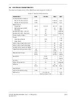
Page 39: ...CHARACTERISTICS Parameter MIN TYP MAX Unit Power supply voltage 9 0 12 0 27 0 V Power Operational mode Sleep mode 950 85 mW mW Power output maximal current 2 0 A Analog output maximal voltage 30 VDC A...

Page 40: ...gger SDI 12 datalogger data line Right 5 PWR1 IN Power supply input 9 VDC to 27 VDC Main power supply V Right 6 GND Power ground Main power supply GND Figure A 2 SDI 12 Adapter to radar wiring Figure...

Page 41: ...s status is not reported unless the user issues a verify command aV The second result returned by aD0 Issued after aV Command will return the last known radar status The following command sequence can...

Page 42: ...e last measurement command has failed the SDI 12 adapter will update the radar status to ERROR If a subsequent verify aV command is issued the adapter will return the last known updated radar status A...

Page 43: ...39 Part 21370 DOCUMENT REVISION HISTORY Revision Date Description 1 08 Oct 2021 Original 2 30 May 2022 Updated information on SDI 12 Adapter and SDI 12 commands in accordance with Jan 2022 reference m...

Reviews: