700-SDI-RADAR-300W-Man Rev 2 30 May 2022
3
/39
Part# 21370
2.3
CONNECTOR PIN-OUT AND WIRING
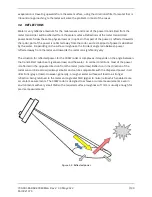
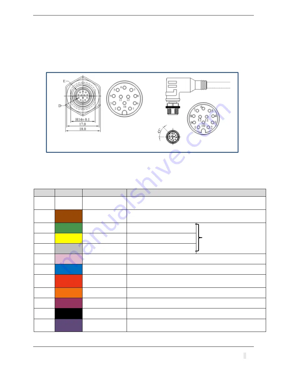
The sensor is supplied with an M12 connector and cable. The connector and cable details are
shown on Figure 2-1. The user is responsible for connecting the sensor to the data collection
platform using the flying leads. Users can attach their own connector, connect the cable via a
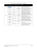
terminal strip, or wire it directly to device electronics. Refer to Table 2-2 for wiring details.
Figure 2-1: Flow meter connectors
Table 2-2: Connector and Cable Pin-out
PIN #
COLOUR
PIN NAME
PIN DESCRIPTION
1
White
GND
This pin should be connected to the ground (negative) pole of
the power supply
2
Brown
+Vin
Power supply. Power supply voltage must be 9 to 22 VDC,
and the power supply must be able to provide at least 0.65W.
3
Green
RS232 – TxD
RS-232 data transmit signal.
RS232 connections only used
when configuring the 300W
sensor with the Geolux
Instrument Configurator
software (see Chapter 5)
4
Yellow
RS232 – RxD
RS-232 data receive signal.
5
Grey
GND
Signal ground.
6
Pink
CAN – H
CAN2.0B high signal
7
Blue
CAN – L
CAN2.0B low signal
8
Red
V+
Output power supply (=Vin) for supply of external optional
equipment and for use with analog 4-20 mA output
9
Orange
RS485 – D-
RS-485 data transmitter/receiver low signal.
10
Dark Red
RS485 – D+
RS-485 data transmitter/receiver high signal.
11
Black
Alarm1 SW
Alarm 1 – open collector switch signal max. 60mA (optional)
12
Purple
4-20 mA
Sink for 4-20 mAanalog interface. Connect sensing device as
pull-up to sink the current


