background image


- 12 -

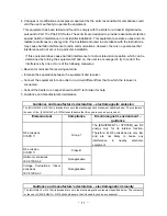
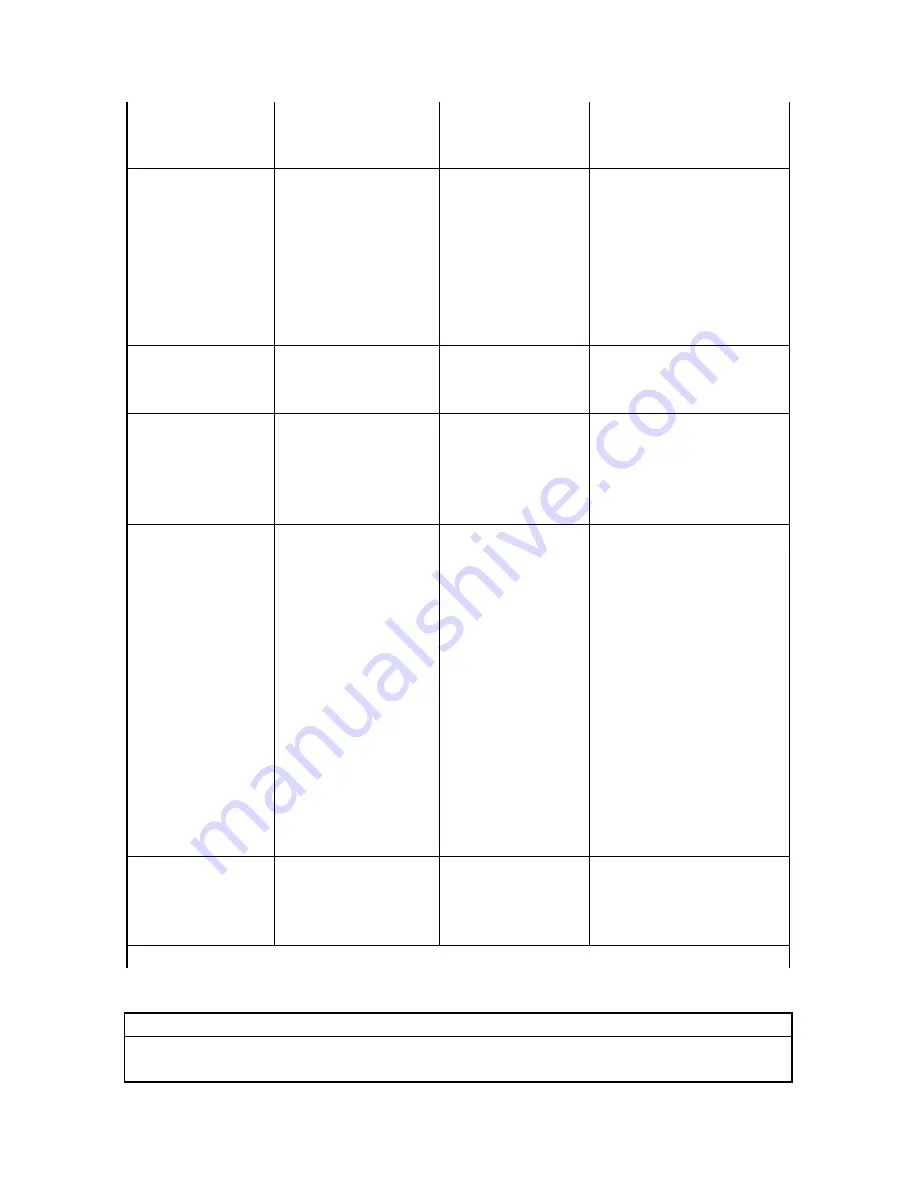
Immunity test 

IEC 60601 test 

level 

Compliance 

level 

Electromagnetic 

environment - 

guidance 

Electrostatic discharge 

(ESD) 

IEC 61000-4-2 

±6 kV contact 

±8 kV air 

±6 kV contact 

±8 kV air 

Floors should be wood, concrete or 

ceramic tile. If floor are covered with 

synthetic material, the relative 

humidity should be at least 30%. If 

ESD interfere with the operation of 

equipment ,counter measurements 

such as wrist strap, grounding shall 

be considered. 

Electrical fast 

transient/burst 

IEC 61000-4-4 

±2 kV for power supply lines 

±1 kV for input/output    lines 


Not applicable 

Mains power quality should be that of 

a typical commercial or hospital 

environment. 

Surge 

IEC 61000-4-5 

±1 kV differential mode. ±2 kV 

common mode 


Not applicable 

Mains power quality should be that of 

a typical commercial or hospital 

environment. 

Voltage dips, short 

interruptions and voltage 

variations on power 

supply input lines 

IEC 61000-4-11 

<5% UT   

(>95% dip in UT) 

for 0.5 cycle 


40% UT 

(60% dip in UT) 

for 5 cycles 


70% UT 

(30% dip in UT) 

for 25 cycles 


<5% UT   

(>95% dip in UT) 

for 5 sec 

Not applicable 

Mains power quality should be that of 

a typical commercial or hospital 

environment. If the user of the 

TL-100Drequires continued 

operation during power mains 

interruptions, it is recommended that 

the TL-100Dbe powered from an 

uninterruptible power supply or a 

battery. 


Power frequency (50Hz) 

magnetic field IEC 

61000-4-8 

3A/m 

3A/m 

Power frequency magnetic fields 

should be at levels characteristic of a 

typical location in a typical 

commercial or hospital environment.

NOTE    UT is the a.c. mains voltage prior to application of the test level. 


Guidance and manufacture’s declaration – electromagnetic immunity

The  

[EQUIPMENT or SYSTEM] i

s

 intended for use in the electromagnetic environment specified below. The customer 

or the user of   

[EQUIPMENT or SYSTEM] 

should assure that it is used in such an environment.


Summary of Contents for FT-F31

Page 1: ...1 Instruction for Use lnfrared Thermometer No contact Type FT F31 BT FT F32 BT FT F41 BT FT F42 BT FT F31 FT F32 FT F41 FT F42...

Page 2: ...r Measuring Temperature 9 Product Specification 10 Common question concerning forehead temperature 2 Product Overview This infrared Thermometer measure the temperature It can get more quick and accura...

Page 3: ...hermometer and then all displayed segments appear briefly as like on Figure 5 2B the displayed screen appears last measured temperature data please see on Figure 5 3B after few seconds automatically c...

Page 4: ...ymbol appear on the display and the temperature unit or blink then it s ready to measure please see on Figure 5 4C Take IR thermometer to aim at the target about 5 to 10 CM distance then press the SCA...

Page 5: ...ll 12 memories recall for FT F31 FT F31 BT FT F32 FT F32 BT Press SCAN button to display M on the displayed screen in the power off condition and then memory recall displays Press again SCAN button ke...

Page 6: ...90 Isopropyl alcohol IPA to clean up before or after use Avoid multiple using by different peoples for cross infection Note 1 Any solution dilution and method other than mentioned above might cause r...

Page 7: ...ressure 86 106 kPa Storage Condition 25 0 55 0 13 0 131 0 Rh 95 Pressure 86 106 kPa Battery type and battery life AAA 2pcs Suitable for FT F31 FT F31 BT FT F42 FT F42 BT AA 2pcs Suitable for FT F41 FT...

Page 8: ...etooth 4 1 BLE Bluetooth Modulation Type GFSK Specially Voice Function for Model no FT F31 FT F31 BT FT F41 FT F41 BT 1 When the IR thermometer is ready you can hear Please measure voice or other lang...

Page 9: ...ermometer for the reading 3 Why is a forehead temperature is more accurate than ear temperature Ear thermometers are considered inaccurate because the positioning of the probe in the ear canal might a...

Page 10: ...anufacturer This device must only be serviced repaired and opened by individuals at authorized sales centers This device is not a life supporting me equipment Statement Clinical accuracy characteristi...

Page 11: ...etween the equipment and receiver Connect the equipment into an outlet on a circuit different from that to which the receiver is connected Consult the dealer or an experienced radio TV technician for...

Page 12: ...nterruptions and voltage variations on power supply input lines IEC 61000 4 11 5 UT 95 dip in UT for 0 5 cycle 40 UT 60 dip in UT for 5 cycles 70 UT 30 dip in UT for 25 cycles 5 UT 95 dip in UT for 5...

Page 13: ...arked with the following symbol Radiated RF IEC 61000 4 3 3 V m 80 MHz to 2 5 GHz 3 V m NOTE 1 At 80 MHz and 800 MHz the higher frequency range applies NOTE 2 These guidelines may not apply in all sit...

Page 14: ...738 1 1 167 1 167 2 333 10 3 689 3 689 7 379 100 11 667 11 667 23 333 For transmitters rated at a maximum output power not listed above the recommended separation distance d in metres m can be estima...

Page 15: ...ng instructions IP22 Symbol for the IP classification Symbol for RF transmitters Manufacturer FUDAKANG INDUSTRIAL CO LTD Address No 8 Yinghe Road Yuanjiangyuan Management Zone Changping Town Dongguan...

Reviews: