19
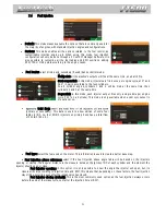
RPM sensor
Select the RPM sensor used on the vehicle, magnetic or Hall Effect.
VR internal ref: this option may only be selected when using a FT500 on
an installation previously made for older ECUs of FT line (FT200, FT250, FT300,
FT350 or FT400), where the shielded cable is a single way (white wire + shield).
VR Differential: Standard option for FT500. Select this for magnetic
less susceptible to electromagnetic interference.
Hall/VR with pull-up: select when using Hall Effect RPM sensor or when
experiencing problems with electromagnetic interference.
RPM Signal Edge:
one is the correct option (without an oscilloscope), select the option Standard (Falling Edge). If the ECU catches no RPM
signal during initial startup, change this parameter to Inverted (Rising Edge).
First tooth alignment: set here the crank trigger alignment related to the TDC. This
alignment can be checked by turning the engine to the cylinder #1 TDC and
counting, counterclockwise, the distance in teeth, from the crank trigger gap to the
RPM sensor.
On engines using distributor and crank trigger (single coil), lock you
distributor at the default position and start the calibration using 45° on 1
st
tooth
alignment. Calibrate the ignition by moving only the timing offset. Do not move the
distributor anymore.
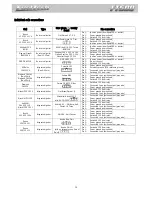
Below is a table with known alignment values and configurations for most of the cases:
Crank trigger - pattern
Engine/brand
Recommended
index position
Ignition
calibration
Cam sync sensor
60-2
BMW, Fiat, Ford (Marelli),
Renault, VW, GM
20º (GM)
15º (others)
GM: -3º
Not mandatory
48-2
Not mandatory
36-1
Ford (FIC ECU)
9
th
tooth
Not mandatory
36-2-2-2
Subaru
5
th
-4,3°
Not mandatory
36-2
Toyota
10
th
tooth
-2,5º
Not mandatory
30-1
Not mandatory
30-2
Not mandatory
24-1
Hayabusa
7
th
tooth
-4,5°
Not mandatory
24-2
Suzuki Srad 1000
Not mandatory
24 (crank) or 48 (cam)
60º
Falling edge
15-2
Moto Honda CB300R
Not mandatory
12+1
Honda Civic Si
7
th
or 11
th
tooth
Not mandatory
12-1
Bikes
Honda/Suzuki/Yamaha
Not mandatory
12-2
Not mandatory
12 (crank) or 24 (cam)
Motorcycles/AEM EPM/
92/95-96/00 Honda
Distributor
Falling edge
8 (crank) or 16 (cam)
Falling edge
4+1 (crank)
Not mandatory
4 (crank) or 8 (cam)
8 cylinders
60°
-10º
Falling edge
3 (crank) or 6 (cam)
6 cylinders
60º
Falling edge
2 (crank) or 4 (cam)
4 cylinders
90º
Falling edge
WARNING: ignition calibration values on this table are just a start point. ALWAYS perform the ignition calibration
according to chapter 16. When the ignition is not correctly calibrated, the timing shown on the ECU screen is different
from the one that is being applied to the engine. This may cause serious damage to the engine.
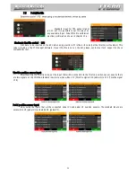
Cam sync sensor
This option indicates if a cam sync sensor will be used and if it uses a hall
effect or magnetic variable reluctance (VR) sensor. This sensor is mandatory when
controlling fuel or timing in sequential mode.
When experiencing electromagnetic interference on VR sensors try changing
-
Automatic cam sync sensor option is a test mode that automatically
assumes a position for the cam sync signal. Use this only for testing purposes, as
this may cause misfires in some applications.


