37
13.5
Crank trigger/RPM sensor
To control fuel and ignition, this ECU is able to read magnetic and Hall Effect sensors.
13.5.1
Distributor
To read RPM signal from a Hall Effect distributor, it should have a sensor with at least 3 pin and have the same
than the engine has number of cylinders
13.5.2
Crank trigger
The crankshaft trigger wheel is responsible for informing the exact position of the crankshaft to the electronic
ignition management system, in such a way that this system is able to determine the ignition timing in the engine. The
trigger wheel is installed on the crankshaft, outside or inside the engine block, with a specific alignment. Usually, the
Crankshaft Trigger Wheels placed on the outside of the block are put in front of the engine, by the front crankshaft pulley,
or in the rear of the engine, by the flywheel. There are many types of Trigger Wheels, but the compatible ones are
mentioned below:
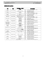
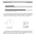
60-2: this is, in general, the most used type of trigger wheel. It is a wheel with 58 teeth and a gap (fault point)
-
Vectra, Omega, etc.), VW (Golf, AP TotalFlex, etc.), Fiat (Marea, Uno, Palio, etc.), Audi (A3, A4, etc.) and Renault
(Clio, Scènic, etc.) models, among other car makers. Ford Flex models with Marelli ECU use this type of trigger
wheel also.
36-2: standard in Toyota engines, being 34 teeth and a gap equivalent to two
missing teeth.
36-1: 35 teeth and a gap equivalent to one missing tooth. It can be found in
all Ford vehicle lines, with 4 or 6 cylinders (except the Flex models with Marelli
injection, which use the 60-2 trigger wheel).
12-Tooth:
distributor. In this case, the cam sensor from the EPM must be used. This distributor has 24 teeth, but as it rotates
half-way for each full engine RPM, there will only be 12 teeth per RPM. Setup the Ignition with 12 teeth at crank
(24 at cam) and the 1
st
tooth alignment with 60°.
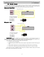
AEM EPM Module Electrical Connections
Red: Switched 12V
Black:
Yellow: red wire from the 2 core shielded cable, white wire must be left disconnected. Setup it as Hall
Effect RPM sensor, falling edge.
White: white wire from the 1 core shielded cable. Setup it as Hall Effect CAM sensor falling edge.
Setup ECU as 12 teeth (at crank) 24 (at cam) and use 60° for 1
st
tooth alignment.
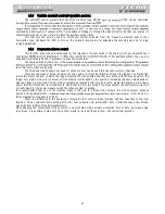
Mitsubishi 1G CAS:
ignition on wasted spark mode and the fuel injection on multipoint or semi-sequential. No sequential fuel or
ignition will work on this CAS with 2 slots on the CAM.
Pin 1 white CAM signal: connect to white wire from FT500 1 core shielded cable (pin 15)
Pin 2 yellow CRANK signal: connect to red wire from FT500 2 core shielded cable (pin 17)
Pin 3 red sensor feed: connect to a sw12V
Pin 4 black
FT500 setup: RPM signal 2 (crank) or 4 (cam) (4G63) or
(6G72), Hall Effect crank and
cam sensors, rising edge on both. Wasted spark ignition. 1
st
tooth alignment: 67°.
Mitsubishi 2G CAS: uses the same settings that 1G CAS, but has a sensor on the crankshaft (reading a 2 tooth
trigger) and a cam sync sensor.
Crank trigger sensor:
Pin 1: switched 12V
Pin 2:
CRANK signal: connect to red wire from FT500 2 core shielded cable (pin 17)
Pin 3:
Cam sync sensor:
Pin 1: switched 12V
Pin 2:
CAM signal: connect to white wire from FT500 1 core shielded cable (pin 15)
Pin 3:


