background image


71 


20.11


Boost control 


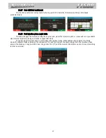
This  feature  allows  the  control,  through  PWM,  of  a  solenoid  valve  that  manages  the  wastegate  valve,  therefore 

regulating  the  boost  pressure.  FuelTech  recommends  using  a  3-way  N75  solenoid.  For  more  information  about  its 
installation, see chapter 14.7 in this manual. 
 

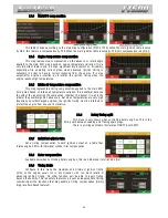
The first parameter to be configured is the TPS percentage, above which the Boost Control will start to pulse the 

control solenoid. When TPS is below the percentage set, the  solenoid remains inactive, allowing the engine to reach the 


-way N75  solenoid, or any other solenoid that maintains the minimum 

boost pressure when inactive. This option is used in most cases. 
 

Lastly, the maps are configured with the percentage of boost based on RPM, where 0% means that the valve is 

wastegate will be closed and the turbine will reach maximum pressure. 

Important note: be very CAUTIOUS when using this  function. When values close to 100% boost have been 

programmed,  the  turbine  may  generate  full  pressure,  which  may  cause  engine  damage  if  it  has  not   been  properly 
prepared to support the pressure levels reached.  

20.12


 Boost activated output 

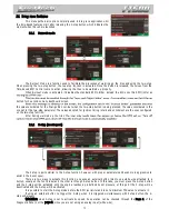
This function is used to activate an auxiliary output according to MAP readings. Setup the range of vacuum/boost 

to activate and to deactivate the output. 


20.13


 Tachometer output 


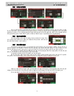
By standard, the tach output is used on gray #8 or a yellow output. 

gray outputs can be used.  


Summary of Contents for FT 500

Page 1: ...Programmable Electronic Fuel Injection and Ignition System Installation and Operation Guide ...

Page 2: ...s for the engine like RPM excess low oil pressure engine temperature among others These alerts can also be programmed to limit the engine RPM or shut it off bringing more security to the end user The unit also has five fully independent calibrations stored onboard allowing different configurations of engines and or cars Ignition can be controlled through distributor or crank trigger Thus it is pos...

Page 3: ...6 9 Electrical installation 27 10 FT500 connection on previous FT installation 29 10 1 Connection on an FT200 FT250 FT300 FT350 installation 29 10 2 Connection on an FT400 installation 29 10 3 Ignition calibration 30 10 4 Injection time differences between FT500 and previous FT ECUs 30 11 Fuel injectors 31 12 Ignition 32 12 1 Ignition with distributor 32 12 2 Ignition with crank trigger 33 13 Sens...

Page 4: ...S idle fuel table 58 18 6 Acceleration fuel enrichment and decay 59 18 7 Engine temperature compensation 60 18 8 Intake air temperature compensation 60 18 9 Battery voltage compensation 60 18 10 MAP TPS compensation 60 18 11 Prime cranking pulse 60 18 12 Engine start 61 18 13 Post start enrichment 61 18 14 Individual cylinder trim 61 18 15 Rotor compensation 61 18 16 Enrichment per gear 61 18 17 G...

Page 5: ...miter 78 22 2 Alerts 78 23 Favorites 79 24 Interface settings 80 24 1 LCD backlight settings 80 24 2 Alert sound settings 80 24 3 Dashboard setup 80 24 4 Startup screen selection 81 24 5 Clear peaks 81 24 6 Protection setup 81 24 7 Measurement units 82 24 8 Demonstration mode 82 24 9 Touchscreen calibration 82 24 10 Serial number and software version 82 25 File manager 83 25 1 FuelTech base map ge...

Page 6: ...s permitted Be informed about local laws and regulations prior to the product installation Important warnings for proper installation of this product Always cut the unused parts of cables off NEVER roll up the excess The black wire of the harness MUST be connected directly to the as well as The use of the 16 way harness is mandatory even when connecting the FT500 on an installation for previous FT...

Page 7: ...on trim per cylinder rotor Fuel and ignition maps by 2D table or 3D table 32x32 points Configurable fuel and ignition map resolution through FT Manager Software and USB cable Fuel injection phase angle control Fuel enrichment and decay adjust Deadtime compensation table by battery voltage Ignition timing compensation by boost vacuum and throttle position TPS Fuel compensation by air and coolant te...

Page 8: ...ckage contents 1 FT500 ECU 1 wiring harness 1 USB flash drive contains FT Manager Software FT guides etc 1 Mini USB cable 1 FT500 installation guide 1 Smart clip support ECU dimensions 141mm 5 5in x 82mm 3 2in x 33mm 1 3in ...

Page 9: ... 1 Gray output 8 White wire from the 2 core shielded cable 8 Magnetic RPM sensor reference Connected to the negative wire of the magnetic sensor When OEM ECU is reading the sensor in parallel split this wire with OEM sensor negative Do not connect when using hall effect sensor Red wire from the 1 core shielded cable 17 RPM signal input Connected to the crank trigger sensor hall or magnetic or to t...

Page 10: ...Gray output 6 These outputs are usually used for ignition control When needed they can be set up as injector outputs or auxiliary outputs Gray 7 4 Gray output 7 Blue 4 6 Blue output 4 These outputs are usually used for injector control When needed they can be configured as auxiliary outputs Blue 5 8 Blue output 5 Black White 9 Power ground inputs Engine ground head block Connect the three black wh...

Page 11: ...outputs the use of a relay is mandatory Yellow outputs 1 to 4 Yellow 1 and 2 or stepper motor control Yellow 1 to 4 Yellow outputs not used for electronic throttle control can be set up as injectors outputs the use of a Peak and Hold driver is mandatory or as auxiliary outputs the use of a relay is mandatory 4 4 Internal MAP sensor This ECU is equipped with an internal MAP sensor Use a 6mm pneumat...

Page 12: ... crank trigger signal injectors and ignition control modes etc 4 In chapter 8 are information about FuelTech Base Map generation 5 The last step before the electric installation Settings st option Wiring harness diagram Check and write down the connections and use it as guide to know how functions were allocated to the pins TIP take photos with a mobile phone 6 Chapters 9 to 15 guide through detai...

Page 13: ...l buttons So all changes on maps setups and functions are done by light touches on the screen To enter menus press the screen twice just like a double click This is a feature that prevents the user from entering the wrong menu when managing the ECU inside the car When entering a map or setting up a function there are some buttons on the screen that act as described below ...

Page 14: ...time condition The center cell is the parameter that is being set up at the moment Click horizontally to navigate through MAP TPS cells Click vertically to navigate through RPM cells 6 2 Dashboard screen When the engine is running the dashboard screen shows real time information of sensors that are being read by the ECU Chapter 24 3 has more information on how to change the instruments on this scr...

Page 15: ...engines with a very light flywheel that accelerates and decelerates quickly during compression strokes at engine startup and running Crank trigger error wrong number of teeth number of teeth is different on the crank trigger wheel than what is set at ECU Electrical noise can cause a reading of a ghost tooth for example Crank trigger error missed tooth reading the ECU detected less teeth then it sh...

Page 16: ...o your engine 4 cylinder engines 1 3 4 2 majority of engines VW AP VW Golf Chevrolet Ford Fiat Honda etc 1 3 2 4 Subaru 1 4 3 2 air cooled VW 5 cylinder engines 1 2 4 5 3 Audi 5 cylinders Fiat Marea 20V and VW Jetta 2 5 6 cylinder engines 1 5 3 6 2 4 GM in line Opala and Omega VW VR6 and BMW in line 1 6 5 4 3 2 GM V6 S10 Blazer 4 3 1 4 2 5 3 6 Ford Ranger V6 8 cylinder engines 1 8 4 3 6 5 7 2 Chev...

Page 17: ... possible as this sensor is faster than the MAP sensor to indicate a quick change of position in the throttle RPM for engine start set up a RPM limit above which the start up routines are disabled Below this RPM all the injection ignition and actuator positions set up for engine start are used 7 2 RPM signal RPM signal is the most important information to run the engine properly This menu is where...

Page 18: ...sync sensor 60 2 BMW Fiat Ford Marelli Renault VW GM 20º GM 15º others GM 3º Not mandatory 48 2 Not mandatory 36 1 Ford FIC ECU 9 th tooth Not mandatory 36 2 2 2 Subaru 5 th 4 3 Not mandatory 36 2 Toyota 10 th tooth 2 5º Not mandatory 30 1 Not mandatory 30 2 Not mandatory 24 1 Hayabusa 7 th tooth 4 5 Not mandatory 24 2 Suzuki Srad 1000 Not mandatory 24 crank or 48 cam 60º Falling edge 15 2 Moto Ho...

Page 19: ...ngle coil per cylinder but do not have a usable Cam Sync input In this case the ECU cannot determine which stroke is compression versus exhaust so Wasted Spark with one coil per cylinder is the proper choice Ignition output select the ignition output edge mode o Falling edge SparkPRO select this option when using FuelTech SparkPRO M W ignition smart coils integrated igniter such as GM LS coils Thi...

Page 20: ...r output fires only a single time per engine cycle 720 on a 4 stroke This mode is only available when a cam sync sensor is properly set up total flow primary or secondary This data is used to allow edition of some fuel tables in lb h I e four 80lb h injectors on primary bank have a total flow of 320lb h 80 x 4 Fuel type select the fuel used on the motor This information is used to create a better ...

Page 21: ...he FT Manager Software If your throttle is not on the list please contact our tech support to check compatibility first Throttle position sensor input After inserting the Throttle code set the input that will be connected to the throttle position sensor usually there are two signals on the throttle Standard inputs are wires white 11 Throttle signal 1A and white 10 Throttle signal 1B Pedal position...

Page 22: ...ns Smooth when cold and normal when hot changes the control mode according to the engine temperature starts with smooth mode and then changes to normal mode automatically Smooth when cold and fast when hot changes the control mode according to the engine temperature starts with smooth mode and then changes to normal mode automatically Operation mode this parameter changes the ratio between the ped...

Page 23: ...tput connected to the valve and the control frequency Small valves usually use up to 2000Hz For big valves use around 80Hz If your valve becomes noisy that the control frequency is lower than what the valve requires In this case increase the control frequency Be aware that the only outputs that can control these kinds of valves are the yellow ones Stepper motor In this option the four yellow outpu...

Page 24: ...harging time There is a dwell table because the charging time varies according to the battery voltage especially in vehicles that do not have alternator Usually the lower the voltage the higher the dwell time has to be set Smart coils coils with internal igniter demand lower charging times These are general values check this parameter with the coil manufacturer Dwell time calculated by the MSD mod...

Page 25: ...en generating a FuelTech base map some basic information is needed Compression ratio used to correctly estimate the timing tables A low medium or high compression ratio is defined according to the fuel used on the engine and if it is turbocharged or naturally aspirated I e a 10 1 compression ratio for a naturally aspirated engine using ethanol Fuel type select information used to calculate a more ...

Page 26: ...d use rubber grommets protectors or any other kind of protective material to prevent any damage to the wires At the engine compartment pass the wires through places where they will not be subject to excessive heat and will not obstruct any mobile parts in the engine Red wire 12V input Being the 12V input to FuelTech ECU this wire must be connected to 12V from a relay Main Relay and cannot be share...

Page 27: ... with a point or in the same point that the ECU black wire This will cause electromagnetic interference and other problems hard to diagnose and to solve The three power grounds 24 and 16 way connectors must have permanent contact with the engine block head never being connected to switches car alarms or others To turn a FuelTech ECU off the red wire should be switched on and off Power ground to ig...

Page 28: ...onnector any other output can be used The connection of the wire that stays in the motor must be changed as follows Yellow 4 must be connected in one of the ways shown below o Magnetic differential that s the most recommended option cause makes the RPM sensor readings most protected against electromagnetic interference Connect the yellow 4 wire on the pin where the shield from the shielded cable w...

Page 29: ...d only once per cycle 720 degrees delivering the total fuel needed in just one pulse In sequential mode it is necessary to understand that the main fuel map and the cranking injection will have fuel injection times near twice the ECU had before Example a map where the idle speed used to have 2 40ms a 1 00ms of injector deadtime will have something around 3 80ms 2 40 x 2 1 00 on sequential mode Inj...

Page 30: ...oint semi sequential or sequential modes Examples of 4 cyl engines running high impedance injectors Individual triggering each blue output controls a cylinder This is the most recommended connection cause is the only one that allows individual per cylinder fuel and ignition compensations amongst other functions Two injectors per channel blue output 1 controls injector of cylinders 1 and 4 Blue out...

Page 31: ...8V 4ms at 10V 3 60ms at 12V and 3 00ms at 15V and check coils temperature at the beginning Capacitive discharge ignition module MSD 6A MSD 7AL Crane Mallory usually the white wire but for MSD the yellow wire is automatically set up as MSD output The installation of ignition modules must always follow what is indicated by its manufacturer in the instructions manual This ignition module will receive...

Page 32: ...l can be set up as injectors outputs Peak and Hold driver is mandatory or auxiliary outputs relay needed Individual coils electrical connections On FT500 these connections must be done by matching the output number with the cylinder number Ignition output 1 controls cylinder 1 coil Ignition output 2 controls cylinder 2 coil Ignition output 3 controls cylinder 3 coil When working with dumb coils an...

Page 33: ...s Integrated igniter Subaru WRX Pin 1 Connected to an ignition output gray wire Pin 2 Power ground engine head Pin 3 Switched 12V from relay Diamond FK0320 Integrated igniter Pajero 3 8 6G75 MiVec Pin 1 Switched 12V from relay Pin 2 Connected to an ignition output gray wire Pin 3 Power ground engine head Hitachi CM11 202 Integrated igniter Fiat Brava Marea 1 8 Pin 1 Switched 12V from relay Pin 2 P...

Page 34: ...V6 Pin 1 Ignition power from SparkPRO or similar Pin 2 Ignition power from SparkPRO or similar Pin 3 Ignition power from SparkPRO or similar Pin 4 Switched 12V from relay Delphi 4 cylinders round Integrated igniter GM Corsa MPFI from 98 to 2002 Pin A Gray 2 cylinders 2 and 3 Pin B Gray 1 cylinders 1 and 4 Pin C Power ground engine head Pin D Switched 12V from relay Delphi 4 cylinders square Integr...

Page 35: ...nected to the battery negative The other to the white 5 wire standard can be changed 13 3 Fuel and oil pressure sensor PS 10B This sensor allows monitoring of fuel or oil pressure in real time through the dashboard screen and internal datalogger With the Check Control function it is possible to program pressure warnings When installing this sensor the PS 10B characteristics Output signal 1 to 5V E...

Page 36: ... models with Marelli injection which use the 60 2 trigger wheel 12 Tooth distributor In this case the cam sensor from the EPM must be used This distributor has 24 teeth but as it rotates half way for each full engine RPM there will only be 12 teeth per RPM Setup the Ignition with 12 teeth at crank 24 at cam and the 1 st tooth alignment with 60 AEM EPM Module Electrical Connections Red Switched 12V...

Page 37: ...core shielded cable 8 Blue Blue Tach 9 Black Yellow Black Yellow 12V input for OEM coil and igniter inside the distributor With external coil do not connect FT500 Setup Engine RPM RPM Signal menu settings RPM sensor VR Differential RPM sensor edge Falling standard Cam sync sensor Variable reluctance Cam sync edge Falling standard Crank trigger wheel 12 at crank or 24 at cam Crank index position 43...

Page 38: ...linder 1 The image below shows a 60 2 trigger wheel with the sensor aligned on the 15 th tooth after gap In this image for example the engine is on the TDC on cylinder 1 Notice that the RPM is clockwise and therefore the TDC on cylinder 1 is set 15 teeth after the sensor passes the gap That is exactly the number of teeth that must be informed to the injection upon its configuration Sometimes a tri...

Page 39: ...ire 2 core shielded cable Magneti Marelli Nº Fiat 464 457 31 Nº Marelli 4820171010 Magnetic Fiat Palio Uno Strada Siena 1 0 1 5 8V MPI Pin red wire 2 core shielded cable Pin white wire 2 core shielded cable Pin S shield 2 core shielded cable Delphi 3 Wires 3 teeth wheel Hall GM S10 4 3 V6 Pin A 5V FT green red wire Pin B battery negative Pin C red wire 2 core shielded cable Fiat engine E TorQ 1 8 ...

Page 40: ...ire Pin 2 white wire 1 core shielded cable Pin 3 shield 1 core shielded cable Denso Suzuki bikes Magnetic Suzuki Hayabusa e Suzuki SRAD Pin 1 white wire 1 core shielded cable Pin 2 shield 1 core shielded cable 3 wires close the small hole with an adhesive Optical Mitsubishi 1 6 16V Pin 1 black shield 1 core shielded cable Pin 2 white red white wire 1 core shielded cable Pin 3 red 5V FT green red w...

Page 41: ... 2s after turning the ignition switch on If this procedure is not respected the engine may be revved up unwittingly during the step motor calibration coming back to normal within seconds If your step motor is different from the ones listed here do what follows 1 Put a tester on the 200 Ohms range 2 Measure the step motor actuators until you find a resistance of approximately 50 Ohms T coils 3 Conn...

Page 42: ...onditioning control the A C button on the dashboard must be connected to a white input of FT500 The two connection options are The air conditioning will remain turned on as long as the A C Signal Input receives signal from the button The signal polarity can be chosen and it varies depending on the installation A C compressor must be controlled with a relay triggered by an auxiliary output sends ne...

Page 43: ... first option is also the most used one in which the fogger injects both nitrous oxide and fuel wet nitrous In the second option the fogger only injects nitrous dry nitrous Fuel enrichment is managed by the injection increasing injection times based on what has been programmed The dry nitrous system has reached better results in tests giving the engine a more linear power than the first option It ...

Page 44: ...ate output and allows the turbine to generate its maximum pressure i e total pressure The higher the counter pressure generated by the turbine at the exhaust manifold the lower its maximum pressure is Wastegate integrated to the turbine This valve has a different operation system as it relieves the boost pressure when pressure is put on its top part which is the opposite of what happens to the was...

Page 45: ...ect them to the signal outputs of the pedal Pedal 1 and Pedal 2 and throttle TPS1 and TPS2 After connecting these inputs it is necessary to calibrate throttle and pedal as guides chapter 16 1 Pins 15 and 16 16 way connector yellow wires will not be used for electronic throttle control they can be set up as auxiliary outputs 15 1 Connection table throttle bodies and pedals On the flash drive provid...

Page 46: ...reach the TPS pins Check with a tester to see if the voltage on the orange wire varies according to the throttle position TPS sensor must be calibrated on the first time the ECU is turned on only and should be recalibrated only when it has to be replaced or the throttle opening on idle was changed TPS calibrations are individual by map file TPS signal voltage must go up as the pedal is pressed and...

Page 47: ...nsor is selected as incorrect use of this function can cause significant error in pressures reported 16 4 Intake air and engine temperature sensors In this menu are the settings for intake air and engine temperature sensors There is a predefined configuration for GM and Fiat sensors but any kind of analog sensor with 0 5V signal can be used This configuration is done through the PC and software FT...

Page 48: ... configuration Compatible analog output scales are Scale Output voltage 0 59 1 10 0 59 0 2V 1 10 4 8V 0 65 1 30 0 65 0 2V 1 30 4 8V 0 65 4 00 0 65 0 2V 4 00 4 8V 0 65 9 99 0 65 0 2V 9 99 4 8V Check your conditioner analog output as there are some not compatible with this ECU For narrowband O2 sensors the readings are shown in Volts O2 sensors 1 and 2 calibration set up the compensation value will ...

Page 49: ...ng setup In the first screen set if the reading is through FT500 sensor input white wire or through FuelTech GearController CAN port d right wheels and number of teeth The next screens will not be displayed when the CAN option is chosen The last setting is related to tire type and size Slick Drag Race tires only require the wheel rim diameter Radial tires require wheel rim diameter tire width and ...

Page 50: ...e a driveshaft RPM sensor instead of screen To calculate wheel speed insert the differential ratio and tire dimensions The last setting is related to tire type and size Slick Drag Race tires only require the wheel rim diameter Radial tires require wheel rim diameter tire width and height 16 9 Gearbox RPM This feature allows the gearbox input shaft RPM Reading The reading is very useful to analyze ...

Page 51: ...ns used to prevent false gear detection due to traction loss Default values are good to most cases The fourth screen is for the RPM drop programming to each gear The fifth screen is to enable and program the timeout for gear shift detection that is another safety feature to prevent false detection The second mode reads an analog gear position sensor which is a potentiometer that indicates the enga...

Page 52: ...ulse to increase the counting This mode cannot detect downshifts and requires the 2 step to be used to reset the counter therefore it is best suited for drag race cars The fifth mode enables an internal counter that is increased by each pulse sent out by the Gear shift output Drag Race Features menu This mode cannot detect downshifts and requires the 2 step to be used to reset the counter therefor...

Page 53: ...n calibration Ignition calibration with distributor When entering this function the ECU shows CALIBRATE THE DISTRIBUTOR UNTIL IT READS 20 or 0 ON THE TIMING LIGHT With this message on the screen point the timing light to the crankshaft TDC mark mark for cylinder 1 Point the timing light and turn the distributor until the ECU Ignition calibration is finished Ignition calibration with crank trigger ...

Page 54: ...ug switch timing light from spark plug If your timing split is 10 you should read 10 BTDC on the damper 10 BTDC and 20 BTDC Ignition Timing Marks For timing lights without the advance retard knob select the 0 option on FT500 TDC 0 and 10 ATDC Ignition Timing Marks After ignition timing calibration is performed your engine is ready for tuning The default map should be a starting point for properly ...

Page 55: ...de the main fuel map editing is a 2D table with an axis for TPS MAP and other for injection time The cell interval may be changed via FTManager Software Advanced mode In this mode main fuel map is a 3D table with TPS MAP ranges X injection time X RPM The cell interval may be changed via FTManager Software 18 2 Overall fuel trim This function adds or removes fuel from the entire map When two indepe...

Page 56: ...duce the compensation for O2 variations Engine temperature for control start is a temperature limit below which the O2 closed loop stays disabled and assumes the open loop fuel tables It is also possible to block the O2 closed loop used i e on engines where the O2 sensor is installed too close to the end of the exhaust reading free air below a certain is a limit to disable the O2 closed loop and r...

Page 57: ...O2 target table to each Pro Nitrous stage which will overwrite the main O2 target table while the auxiliary control is on This feature is only enabled when all Pro Nitrous requirements are fulfilled Aux Pro Nitrous by time This feature is a 16 points time based O2 target table to each Pro Nitrous stage which will overwrite the main O2 target table while the auxiliary control is on This feature is ...

Page 58: ...ime If on the other hand the TPS variation were only 20 only half of the max fuel pump will be added Engines equipped with small throttles usually need a higher TPS variation to need max fuel pump In this case use higher TPS values on this parameter 70 90 For big diameter throttle bodies a small TPS variation is enough to demand max fuel pump around 15 Accel fuel pump reduction above TPS 50 due to...

Page 59: ...urized the temperature rises immediately to very high numbers In cars with intercooler the ideal mixture can be used from intercooler inefficiency situations low speed on 18 9 Battery voltage compensation With lower battery voltages the injectors takes a longer time to open and to close This table is used to compensate this variation Fuel injectors with a high flow rate usually operate with minimu...

Page 60: ...inder For that reason it is ideal to power the ECU ignition key switch If the engine temperature sensor has not been installed only the value from start injection with cold engine is considered 18 13 Post start enrichment This configuration is a table that relates engine temperature with time in seconds This parameter helps stabilizing engine RPM just after start improving the idle control especia...

Page 61: ...ectors opens or closes and is only available when the fuel injection is being controlled in sequential mode To explain what this phase angle is think about the ignition timing When talking about ignition the timing means the angular distance between the combustion TDC and the moment the spark plug ignites The injection phase angle is the distance in degrees BTDC from the ignition TDC 0 until the m...

Page 62: ...n this table are subject to all the other compensations by temperature battery voltage etc Advanced mode In this mode the main ignition table is a 3D map that relates RPM x MAP x ignition timing 19 2 Overall ignition trim To apply a quick compensation to the entire ignition map the Overall Ignition Trim function may be used It is only necessary to inform the correction negative or positive and con...

Page 63: ...colder the air entering the combustion chamber the denser it is and the greater the possible ignition advance is But when temperatures are very high especially on turbocharged engines the ignition timing must be retarded to protect the engine from knock or detonation 19 6 Rotary timing split This menu is only shown when controlling Rotary engines This is the timing split between Leading and Traili...

Page 64: ...tion so the retard can happen Right after FT500 detects a gear change the ECU will compensate the timing according to the programmed There is also a ramp return time that will interpolate the compensated timing to have a smooth gear shift and preserve transmission In the example below there will be a 5º timing retard The ramp return time is the retard total time which will be gradually re establis...

Page 65: ...rted only when the programmed RPM is reached If a button on the dashboard is preferred select it on the internal datalogger datalogger button on a spot Log is automatically stopped when memory is full ECU is turned off or the button is pressed Sampling rate The sample rate defines log quality Higher the sample rates created more detailed logs however the logging time available will be shortened Fo...

Page 66: ... set up later according to engine temperature This option is recommended for engines with high profile camshafts where the automatic idle control is not able to stabilize idle RPM Actuator reaction level this parameter is the aggressiveness that the timing and the actuator will be changed of position in order to control a RPM fall The higher this number the more aggressive is the reaction of the c...

Page 67: ...On the opposite case when setting a very high RPM there will not be significant fuel economy gains delay before fuel is actually cut off after releasing the throttle Such delay exists to avoid the engine to instantly become lean when the throttle is released It also rapidly cools the combustion chamber without being excessive and avoids situations in which the cut off might oscillate especially wh...

Page 68: ...w considerable load a fuel compensation is also available 20 7 Air conditioning To control air conditioning through FT500 first you have to setup an output to control the A C relay Then setup the input that will receive signal from the A C button on the car dashboard Check chapter 14 2 for more information 20 8 Fuel pump This output activates the fuel pump by grounding the relay that controls the ...

Page 69: ...us only through pulse width modulation PWM sent to the solenoids The first parameter to be configured is the TPS opening percentage above which the injection of nitrous will be activated The next parameter is the percentage of fuel enrichment for 100 nitrous Such percentage is applied to injection times making them longer in order to keep up with the engine The ignition retard is applied to the en...

Page 70: ...st pressure when inactive This option is used in most cases Lastly the maps are configured with the percentage of boost based on RPM where 0 means that the valve is wastegate will be closed and the turbine will reach maximum pressure Important note be very CAUTIOUS when using this function When values close to 100 boost have been programmed the turbine may generate full pressure which may cause en...

Page 71: ...timing retard and enrichment are the ones configured on the two step function After having warmed up the tires 21 2 3 step boost spool The 3 step is quite similar to the 2 step function however with proper parameters and even more aggressive to assist in the boost spool There are two ways to activate this function one uses an external button must use a white wire attached to a button usually on th...

Page 72: ... value for all the gears or different RPM for each gear just like the shift light feature The main difference is that the gear shift feature has an extra option to shift the first gear by time after the launch and the next gears by RPM RPM shift will only happen after the 2 step switch off After the last gear you must switch on the 2 step again to reset the function To enable this feature the gear...

Page 73: ...wn in the image above This function is frequently used in drag racing cars because it makes it easier to control the vehicle once it allows the traction to be recovered through an ignition cut ramp It is a passive traction control and therefore some attempts must be made before finding the perfect adjustment considering the characteristics of the car and the quality of traction provided by the tra...

Page 74: ...eed or the driveshaft RPM and applies ignition compensation according to the two RPM curves A and B to control launch The basic idea is to retard the ignition timing reducing power to the wheels When the wheel speed reaches the programmed in the speed curve A the ECU starts the programmed retard in the delay curve A point As the speed increases and goes toward the curve B speed the retard applied ...

Page 75: ...t be turned on In other words the vehicle must launch in less than 15s after 2 step deactivation 3 TPS must be above minimum configured 4 RPM must be inside RPM activation window With these 4 requirements fulfilled the Pro Nitrous stages will start and follow the configured time The fuel and timing compensations will also start at this point If any condition fail the Pro Nitrous is deactivated and...

Page 76: ... different fuel compensation to each cylinder and stage It is also possible to compensate the fuel injection considering the bottle pressure Low bottle pressure requires less fuel Nitrous stage timing tables The ignition After the delay there are the timing tables to each stage You can program the timing compensation over RPM and it is calculated considering the main timing table In the FTManager ...

Page 77: ...continues to work normally Safe mode besides the alert displaying on the screen engine has its max RPM limited to wha rev Engine shut off besides the alert displayed on the screen engine is immediately shut off by fuel and ignition cut Shift alert When engine reaches the RPM set on this parameter an alert can be shown at the dashboard and or an auxiliary output can be activated to control an exter...

Page 78: ...r the base fuel pressure The base fuel pressure is what the pressure regulator should keep with MAP 0 psi that in most of cases is 45psi with the engine turned off and the fuel pump turned on When engine is turned on the vacuum boost makes the fuel pressure regulator to manage the fuel pressure in a 1 1 ratio 23 Favorites In this menu it is possible to have access to the most used functions of the...

Page 79: ...e are 24 configurable positions on the dashboard with minimal size of 1x1 possible to select sizes as 1x2 2x1 and 2x2 First select the position where you want the information to be then the reading that will be displayed and the reading size Exhibition limits and alerts On some sensors maximum and minimum values may be set up to activate alerts on the dashboard In this case the sensor changes his ...

Page 80: ...e start only All menus are open for visualization and tuning but the injection system is blocked until a password is inserted Protect adjust and engine start in this mode engine start and the visualization and changing of all ECU parameters are blocked until a password is inserted When touching the screen to enter the menu and a password has already been set and protecting the menus the system wil...

Page 81: ...ow the main features of FuelTech FT500 and its working You can set the waiting time to get in the demo mode To exit just touch the screen 24 9 Touchscreen calibration This function allows the touchscreen recalibration use it whenever you notice the screen is unresponsive Calibrate the screen with you finger or with a pen 24 10 Serial number and software version In this menu it is possible to verif...

Page 82: ... the engine needs Before using this function make sure you have followed chapter 5 in this guide 25 2 Edit map file name Edit the file map name after generating the FuelTech base map 25 3 Copy map to another file This option copies a map that is already setup to an empty position or to overwrite a previous map First select will be copied is not shown only the positions available to be overwritten ...

Page 83: ...d timing split parameter This means that if the ignition timing in the main table is 0 and timing split is 10 the ECU will fire the leading coil at 0 and the trailing coil 10 after leading coil was fired 26 1 Crank angle sensor installation and alignment The Crank Angle Sensor needs to be installed in the engine at 0 top dead center position To align it follow this quick step by step 1 Use your ig...

Page 84: ...rtant to correctly setup the ECU based on your engine It is possible to do it by the ECU screen but we strongly recommend you to use the FT Manager Software to go through this initial setup Below are only basic steps to rotary engines Please be sure to follow the step by step on chapter 7 to correctly setup your ECU Under the RPM Signal menu these are settings to rotary engines RPM sensor VR diffe...

Page 85: ...el 2 Gray wire C Trailing rotor 1 Coil T1 Channel 3 Gray wire D Trailing rotor 2 Coil T2 Channel 4 For 3 rotor engines the gray wires are connected as the table below shows ECU Ignition Output Function Recommended SparkPRO 6 Channel Gray wire A Leading rotor 1 Coil L1 Channel 1 Gray wire B Leading rotor 2 Coil L2 Channel 2 Gray wire C Leading rotor 3 Coil L3 Channel 3 Gray wire D Trailing rotor 1 ...

Page 86: ...87 27 FT500 electrical diagram 27 1 FT500 4 cylinders sequential fuel SparkPRO 2 wasted spark coil ...

Page 87: ...88 27 2 FT500 4 cylinders sequential fuel SparkPRO 4 coil on plug ...

Page 88: ...89 27 3 FT500 2 rotors sequential fuel SparkPRO 4 ...

Reviews: