background image

21

20

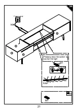
Power supply

Please press the switch to

control the light

12

12

1

2

M1

M2

N&P

x1

M1

M1

Summary of Contents for KF210173-01

Page 1: ...RODUCT INSTRUCTION KF210173 01...

Page 2: ...r restraints only reducts but does not eliminate the risk of tip over Never open more than one drawer at a time MAINTENANCE TIPS To avoid dulling of finish do not place furiture in direct sunlight Nev...

Page 3: ...Safety information Important information Please read closely and carefully Save this information GB 3...

Page 4: ...CORRECT WRONG Quickfit head should be in the centre of the cam lock when the two panels are joined Cam lock should be inserted before quickfit CAM LOCK 4...

Page 5: ...D x24 E x16 F x16 x10 H x10 I 6x35mm 15x10mm 4x40mm 3x12mm 5 Hardware List G x2 L 2 spare x2 CL x2 CR L300mm L300mm x2 DL L300mm x2 DR L300mm x1 M x1 x1 P N x8 J x2 K 1 spare 2 spare 1 spare 1 spare 3...

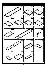
Page 6: ...6 Parts List x2 1 2 3 4 5 6 7 8 9 10 10 10 10 11 12 13 14 15 16...

Page 7: ...7 1 x1 2 x1 3 x1 4 x1 5 x1 6 x1 7 x1 8 x1 9 x1 x4 10 x1 11 x2 12 x2 13 x2 14 x2 15 x2 16...

Page 8: ...8 01 02 6 7 6 CR CR 7 CL CL 8 8 8 6 7 8 7 90 6 7 C C C C D D D D E E E E E E x4 C 6x30mm x6 E 3x12mm x1 CL x1 CR L300mm L300mm CL CR x4 D 4x40mm...

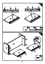
Page 9: ...9 03 04 4 CL CL 5 CR CR 4 5 8 6 7 4 5 C C C C C C C C E E E E E E x6 E 3x12mm x1 CL x1 CR L300mm L300mm CL CR x8 C 6x30mm...

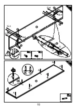
Page 10: ...10 05 06 9 9 10 10 10 10 10 10 9 1 1 A A A A A A A A F F F F Fx4 Fx4 Fx4 G G G G Gx4 Gx4 Gx4 x16 F x16 G x8 A 6x35mm...

Page 11: ...11 07 5 5 7 8 6 6 9 9 4 4 90 4 D D D D D D D D x8 D 4x40mm...

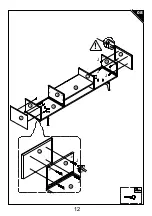
Page 12: ...12 08 5 9 8 6 7 4 2 3 3 4 2 9 J J J J J J J J x8 J 4x25mm...

Page 13: ...3 09 Tear off the back glue of the light strip Take out the light wire of N 8 8 7 6 9 5 2 back The light wire N can be installed on the left and right behind plate 8 K L N N N N N x1 L x1 K x1 N L550m...

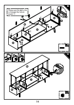
Page 14: ...14 10 11 5 7 8 6 2 9 4 3 Please put the light wire m through the hole in board 11 11 5 3 8 6 2 9 5 1 1 2 3 7 5 11 B B B B B B B B C C C C C C C C x8 C 6x30mm x8 B 15x10mm...

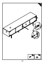
Page 15: ...15 12 x10 x10 1 11 3 2 9 I H I I I I I I I I I I x10 H x10 I 3x16mm...

Page 16: ...ut the light wire of P Tear off the back glue of the light strip 9 9 The light wire P can be installed at the bottom of plate 9 on the left and right 2 4 1 8 10 10 10 10 7 6 3 K L P P P P P x1 P L1000...

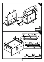
Page 17: ...17 14 15 1 2 5 9 6 7 1 2 3 x2 x2 12 12 12 14 14 13 A A A A B B B B x8 A x8 B 6x35mm 15x10mm...

Page 18: ...18 16 17 12 14 14 13 13 16 15 15 x2 x2 15 14 13 12 x2 13 14 DR DL D D D D E E E E E E x8 D 4x40mm x2 DL L300mm x2 DR L300mm DL DR x12 E 3x12mm...

Page 19: ...19 18 DL CL 12 12 1 2 14 14 13 13 16 16...

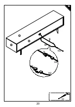
Page 20: ...20 19 1 11 3 M2 M2 M2 N P P N x1 M2 M2...

Page 21: ...21 20 Power supply Please press the switch to control the light 12 12 1 2 M1 M2 N P x1 M1 M1...

Page 22: ...sible for anchoring the items to the wall and for the materials used for that purpose Please observe the maximum load capacity as specified in the assembly instructions Keep the bag containing the fit...

Reviews: