background image

1/28

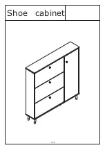
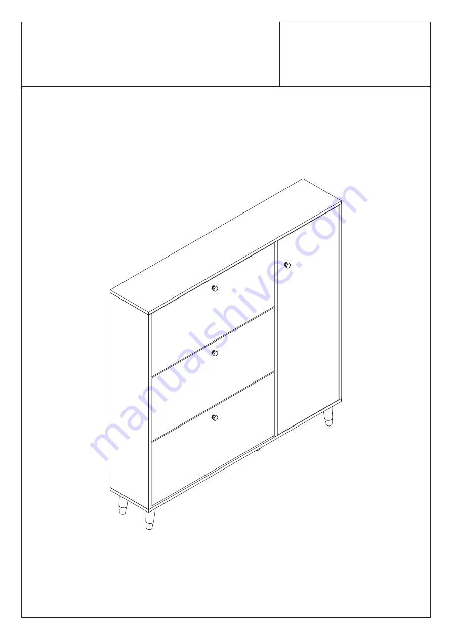
Shoe cabinet

Summary of Contents for LJY-KF210118-02

Page 1: ...1 28 Shoe cabinet...

Page 2: ...with a rag dampened with water glass cleaner and then dry with a dry rag Do not use an electric screwdriver and do not use too much force when installing because the board is easy to break IMPORTANT O...

Page 3: ...4mm 4x40mm 3 5x14mm 3 5x14mm 4x10mm E 1 E 2 G 1 G 2 G 3 M 1 M 2 4x14mm Nx4 N 1 N 2 6x30mm 4x40mm Ox2 Px12 Please prepare the following tools When installing please carefully confirm whether each screw...

Page 4: ...4 28 Qx1 Rx8 Sx1 1 2 3 4 5 6 7 8 9 10 11 12 13 13 13 14 14 14 14 15 16 16 17 18 18 19 19 19 19 19 19 20 20 20 21...

Page 5: ...6x35mm Tighten Cam Bolt A to panel 2 and panel 4 as shown 2 2 4 A A A A A A 2 Please hammer the G 1 and G 2 onto the 2 and 3 boards as shown 2 4 G 1 G 1 4 4 G 2 Gx6 G 1 G 2 G 1 G 1 G 1 G 1 G 2 G 2 G...

Page 6: ...d No 7 board respectively then Lock with Cam Lock B with No 2 board and No 4 board respectively as shown 4 2 Back Back Front Front 7 6 5 B C 180 5 2 B B B B B C C C C 7 6 5 2 4 Back Please note that t...

Page 7: ...Cam Bolt A to panel 1 as shown 2 Please use screw J to lock with Iron Sheet F and plate No 8 respectively as shown 1 1 A A A A A A A A A 8 8 J J J J J F F F F J J J J J J J J J J J J J J J Ax9 6x35mm...

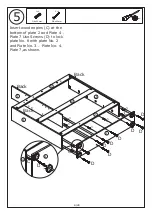
Page 8: ...ins C at the bottom of plate 2 and Plate 4 Plate 7 Use Screws D to lock plate No 8 with plate No 2 and Plate No 3 Plate No 4 Plate 7 as shown 3 4 2 5 6 7 8 Back Back Back C C C C C C C C D D D D D D D...

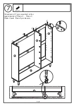
Page 9: ...2 6 7 14 14 14 14 8 14 8 15 15 F Q 5 3 Please turn the number 14 pin to the plate F screw lock respectively Please rotate number 15 pin to number 8 board Please use adjustment pad Q to rotate number 1...

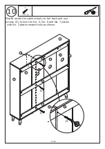
Page 10: ...10 28 7 Cx8 Wood pins C are inserted in the upper parts of Plate 2 Plate 3 Plate 4 and Plate 5 as shown 2 4 3 5 8 C C C C C C C 4 C 6x30mm 6 7 15 Q 8 15 14 14...

Page 11: ...1 28 8 9 2 8 7 3 4 12 11 10 13 13 13 9 10 11 12 13 13 13 Insert number 9 number10 number 11 and number 12 back plate into the back plate slot of number 2 left side plate and 4 right side plate as show...

Page 12: ...12 28 9 180 4 4 3 2 1 5 B B B B B B B B B Lock Panel 1 with Panel 2 Panel 3 Panel 5 and Panel 4 with Cam Lock B as shown Bx9 15x10mm III II I...

Page 13: ...13 28 Dx3 10 4 2 1 3 5 6 7 9 10 11 12 Please rotate the cabinet body to the back and use screws D to lock the No 5 No 6 and No 7 plates with No 3 plates respectively as shown 4x40mm D D D 5 3...

Page 14: ...Please use screw J to lock back plate No 9 No 10 No 11 No 12 and No 6 respectively as shown 14 28 11 1 2 3 4 8 9 10 11 12 6 Jx8 4x14mm 6 J J J J J J J J...

Page 15: ...vely and place No 16 board on the movable tray R as shown 15 28 12 Rx8 1 8 2 3 4 16 16 4 R R R R R R R R 16 13 Please fasten the hardware hinge O to plate No 17 with a screw P as shown Please fasten t...

Page 16: ...16 28 14 Please fasten plate 17 with plate 4 with a screw P as shown 17 1 2 3 4 P P P P O 4 17 Px4 P P P P O O O O O Px8 16 16 3 5x14mm...

Page 17: ...ease fasten the E 1 E 2 and No 18 plates with screws H respectively as shown 2 Please fasten the E 1 E 2 and No 20 plates with screws H respectively as shown H H H E 2 H H H E 1 E 18 18 18 x2 18 E 1 E...

Page 18: ...fasten the E 1 E 2 and No 19 plates with screws H respectively as shown 2 Please fasten the screw L through the 18 plate and the handle k as shown 19 18 H 19 E 1 E 1 E 2 H x2 1 2 18 E 1 18 K L x2 Hx4...

Page 19: ...E 1 E 2 and No 21 plates with screws H respectively as shown 2 Please fasten the E 1 E 2 and No 20 plates with screws H respectively as shown 21 E 1 H H H H H H E 2 21 21 E 1 21 E 1 E 2 20 E 1 H 20 2...

Page 20: ...ase fasten the E 1 E 2 and No 19 plates with screws H respectively as shown 2 Please fasten the screw L through the 21 plate and the handle k as shown 1 21 E 2 H E 1 19 H 19 E 1 21 K L 21 E 1 Hx2 Kx1...

Page 21: ...E 21 E E 21 Please use screw I to lock G 3 through plate E 1 and No 2 and plate E 2 and No 3 respectively as shown Note Please note that the front panel of drawer No 18 is different from No 21 Plate...

Page 22: ...22 28 20 Please insert panel 19 into the cabinet as shown 21 18 1 3 2 E 2 E 2 E 1 E 1 19 19 19...

Page 23: ...23 28 21 Please use screw H to lock the E 1 and E 2 with plate 19 respectively as shown H E 1 13 E 1 E 1 E 2 E 2 H H H 21 18 19 19 1 2 3 Hx4...

Page 24: ...tation then use a hammer to knock N 1 against the wall and use screws N 2 to pass through plate 5 and Plate 9 and Plate 12 to lock with the wall as shown drilling hole 6x30mm WALL WALL x2 N 1 x2 x2 WA...

Page 25: ...1 and No 2 and plate E 2 and No 3 respectively as shown WALL 21 18 18 2 3 1 E 2 G 3 I G 3 I E 1 Option Gx2 Ix2 G 3 4x10mm Please use screw I to lock G 3 through plate E 1 and No 2 and plate E 2 and N...

Page 26: ...26 28 24 Option Option WALL 18 18 21 3 2 E 1 E 2 Please insert panel 19 into the cabinet as shown 19 19 Please insert panel 19 into the cabinet as shown 18 18 21 2 19 E 2 E 1 19...

Page 27: ...use screw H to lock the E 1 and E 2 with plate 19 respectively as shown Hx2 WALL 19 E 2 E 1 H E 1 19 H 18 18 21 Please use screw H to lock the E 1 and E 2 with plate 19 respectively as shown H 18 18...

Page 28: ...position on the wall use the impact rotation guide hole position then use the hammer to hit N 1 the wall use the screw N 2 to pass through the cloth to lock with the wall as shown x2 x2 x2 WALL WALL W...

Page 29: ...or health reasons For other reasons if the furniture needs to be returned it must be cleaned and dried and operated within 30 days of receipt Type of Warranty Claim Failure to follow the furniture ins...

Page 30: ...eive an order with obvious shipping damage from the retailer then we suggest the delivery is refused If the delivery has been accepted and then shipping damage is found please follow the specific inst...

Reviews: