WWW.FUHR.DE
833/833SP
autosafe
835/835SP
autosafe
• Einsetzbar für Elemente aus Kunststoff, Holz, Alumi nium
und Stahl.
• Flügel und Rahmen müssen auf der gesamten Höhe parallel
verlaufen.
• Es sind ausschließlich Profilzylinder gemäß DIN 18252
einzusetzen.
• Ausfräsung für die Schlosskästen gemäß Zeichnung.
• Ausfräsung für Profilzylinder und Drücker müssen fluchten.
•
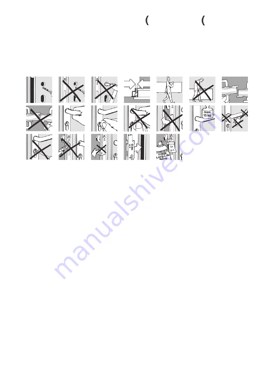
Beschlagbohrungen niemals bei eingebautem Schloss
vornehmen.
• Vor dem Einbau des Schlosses sind sämtliche Verun reini-
gungen z. B. Späne aus dem Fräsbereich zu entfernen.
• Stulpe und Schließteile durch Schrauben mit ø 4 mm, Länge
dem Profilsystem angepasst, befestigen.
• Die Montageschrauben müssen rechtwinklig zur Stulpe
positioniert eingedreht werden.
• Exakten Sitz der Schließteile gemäß Zeichnung beachten.
• Beim Anziehen der Stulpschrauben darauf achten, dass sich
die Treibstangen frei bewegen können.
• Für SKG-geprüfte Kunststoff-Elemente: Stulpe und Schließ-
teile durch mindestens zwei Schrauben (ø 4 mm) mit dem
Verstärkungsprofil verbinden.
•
Für SKG-geprüfte Aluminium-Elemente: Stulpe und
Schließteile durch Schrauben mit ø 4 mm, Länge dem Pro-
filsystem angepasst, mit dem Aluminium-Profil befestigen.
• Für SKG-geprüfte Holz-Elemente: Stulpe und Schließteile
durch Schrauben mit ø 4 mm, Länge 40 mm, befestigen.
• Bei evtl. Schwergängigkeit einer Funktion nach Montage
des Schlosses niemals gewaltsam vorgehen! Stattdessen ist
die Ursache zu ergründen und abzustellen.
• Beim Transport der Türen – auch bei verriegeltem Schloss –
den Flügel vor Verschiebung schützen.
• Applicable for elements made of PVC, timber, aluminium
or steel.
• Door leaves and frame must run in parallel throughout the
entire height.
• Solely profile cylinders according to DIN 18252 have to be
installed.
• Mortise for the lock cases as per drawing.
• Mortise for the profile cylinder and lever must be in align-
ment.
• Never drill the fitting when the lock has been installed.
• All contamination such as shavings as a result of drilling
must be removed prior to the installation of the lock.
• Attach faceplate and strike plates with screws of a 4 mm
diameter and a length matching the profile system.
• Fixing screws have to be positioned perpendicular to the
faceplate.
• Observe exact position of the strike plates as per drawing.
• Observe by fixing the faceplate screws that the rods must
have the room to move freely.
•
For SKG-certified PVCu doors: Connect faceplate and
strike plates to the reinforcing profile with at least two
screws (ø 4 mm).
• For SKG-certified aluminium doors: Attach faceplate and
strike plates with the aluminium profile with screws of a
4 mm diameter, length matching to the profile system.
• For SKG-certified timber doors: Attach faceplate and strike
plates with screws of a 4 mm diameter and 40 mm in
length.
• Do not use force in the event of tightness or sluggish op-
eration after the lock has been installed! The cause of the
problem should be ascertained and remedied instead.
• Suitable protection must be applied to the door leaves
during transportation even if the locks are bolted.
Einbau- und Befestigungsanweisungen
Installation and fixing instructions
2 -
6 mm
6


