background image

1.3  Precautions for Using dynamic breaking unit 

This section provides precautions in introducing dynamic breaking units, e.g. precautions for installation environment, power 
supply lines, wiring, and connection to peripheral equipment. Be sure to observe those precautions. 


1.3.1  Installation environment 

Install the dynamic breaking unit in an environment that satisfies the requirements listed in Table 1.3-1. 

Table 1.3-1  Environmental Requirements 

Item Specifications 

Site location 

Indoors 

Ambient temperature 

-10 to +40

Relative humidity 

5 to 95% (No condensation) 

Atmosphere The 

dynamic breaking unit

 must not be exposed to dust, direct sunlight, corrosive gases, 

flammable gases, oil mist, vapor or water drops. 
Pollution degree 2 (IEC60664-1) 

(Note 1)


The atmosphere can contain a small amount of salt. (0.01 mg/cm

2

 or less per year) 

The 

dynamic breaking unit

 must not be subjected to sudden changes in temperature that will 

cause condensation to form. 

Altitude 

Less than 1,000 m 
If the altitude is 1,000 to 3,000 m, output current derating is required. 


If the altitude is 2,001 to 3,000 m, the insulation level of the control circuits lowers from the 

reinforced insulation to the basic insulation. 

Vibration 

Compliant to the standard IEC61800-2 
Amplitude  0.3 mm:  2 to less than 9 Hz 
 1 

m/s

2

:  9 to 200 Hz 

Compliant to the standard IEC61800-5-1 
Amplitude  0.075 mm:  10 to less than 57 Hz 
 

1 G: 

57 to 150 Hz 


(Note 1)

    Do not install the dynamic breaking unit in an environment where it may be exposed to lint, cotton waste or moist dust or dirt 

which will clog the heat sink of the dynamic breaking unit. If the dynamic breaking unit is to be used in such an environment, install it in a 
dustproof cabinet. 

Summary of Contents for BUC S-69D

Page 1: ...ration a short life or even a failure of this product Deliver this manual to the end user of this product Keep this manual in a safe place until this product is discarded For the installation and selection of peripheral equipment exclusive to the stack type of inverters refer to the FRENIC VG User s Manual Stack Type Edition For the configuration of the inverter functions and operating procedure r...

Page 2: ...eproduced or copied without prior written permission from Fuji Electric Co Ltd All products and company names mentioned in this manual are trademarks or registered trademarks of their respective holders The information contained herein is subject to change without prior notice for improvement ...

Page 3: ...age 5 Chapter 2 MOUNTING AND WIRING 6 2 1 Mounting the dynamic breaking unit 6 2 1 1 Terminal Arrangement and Screw Sizes Main circuit terminals 7 1 Rank 4 500 kW 7 2 2 Wiring 8 2 2 1 Connection diagram 8 2 2 2 Removing and mounting the front cover and the wiring guide 10 2 2 3 Basic Connections 11 2 2 4 Main circuit terminals 11 1 Screw specifications and recommended wire sizes main circuit termi...

Page 4: ...pection 26 5 4 List of Periodic Replacement Parts 27 5 5 Insulation Test 27 5 6 Inquiries about Product and Guarantee 28 5 6 1 When making an inquiry 28 5 6 2 Product warranty 28 1 Free of charge warranty period and warranty range 28 2 Exclusion of liability for loss of opportunity etc 29 3 Repair period after production stop spare parts supply period holding period 29 4 Transfer rights 29 5 Servi...

Page 5: ...er purposes directly related to the human safety Though the dynamic braking unit is manufactured under strict quality control install safety devices for applications where serious accidents or property damages are foreseen in relation to the failure of it An accident could occur Installation Install the dynamic braking unit on a base made of metal or other non flammable material Otherwise a fire c...

Page 6: ...Doing so could cause an accident or an electric shock Before changing the slide switches on the control printed circuit board turn the power OFF wait at least ten minutes and make sure that the charging lamp are turned OFF Further make sure using a multimeter or a similar instrument that the DC link bus voltage between the terminals P and N has dropped to the safe level 25 VDC or below An electric...

Page 7: ...o could cause an electric shock or injuries Disposal Treat the dynamic braking unit as an industrial waste when disposing of it Otherwise injuries could occur General precautions Drawings in this manual are illustrated without the front cover or safety shields for explanation of detail parts Do not turn the power ON when the dynamic braking unit is as shown in drawings Be sure to restore the cover...

Page 8: ......
Page 9: ...n Nameplate b Sub Nameplate Figure 1 1 1 Nameplates BUC500S 69D 1093V DC 594A 500kW CONT 135 kg BUC500S 69D TYPE Type of the dynamic breaking unit BUC 500 69 D S Product Type BUC Rated output Structure S stack type Voltage class 69 690V Series name BUC D series SOURCE Power ratings OUTPUT rated output capacity MASS Mass of the dynamic breaking unit in kilogram SER No Product number 2 8 A 4 5 6 A 0...

Page 10: ...le φ26 Cooling fans N bar P bar Handle Warning plate Handle Front cover Hoist holes φ26 Controle circuit terminal block Casters Sub nameplate Hoist hole φ26 Main nameplate Charge lamp Figure 1 2 1 Rank 4 500 kW 2 Warning plates and label Figure 1 2 2 Warning Plates and Label 2 ...

Page 11: ...te 1 The atmosphere can contain a small amount of salt 0 01 mg cm 2 or less per year The dynamic breaking unit must not be subjected to sudden changes in temperature that will cause condensation to form Altitude Less than 1 000 m If the altitude is 1 000 to 3 000 m output current derating is required If the altitude is 2 001 to 3 000 m the insulation level of the control circuits lowers from the r...

Page 12: ...f fibrous or paper dust Fibrous or paper dust accumulated on the heat sink lowers the cooing effect Entry of dust into the dynamic breaking unit causes the electronic circuitry to malfunction Any of the following measures may be necessary Mount the dynamic breaking unit in a sealed cabinet that shuts out dust Ensure a maintenance space for periodical cleaning of the heat sink in cabinet engineerin...

Page 13: ...d in Table 1 3 2 wrap the dynamic breaking unit in an airtight vinyl sheet or the like for storage 3 If the dynamic breaking unit is to be stored in a high humidity environment put a drying agent such as silica gel in the airtight package described in 2 above 2 Long term storage The long term storage method of the dynamic breaking unit varies largely according to the environment of the storage sit...

Page 14: ... and Table 2 1 1 When mounting two or more dynamic braking units side by side observe also the clearances specified in Table 2 1 1 6 E B C D A Figure 2 1 1 Mounting Direction and Required Clearances Table 2 1 1 Clearances mm A B C D E Rank 4 500 kW dynamic braking unit size Between dynamic braking units Rank 4 10 10 300 350 20 With other equipment 20 50 350 100 50 Dynamic braking units cannot be m...

Page 15: ...ank 4 500 kW Internal front view Right side view Unit mm For external braking resistor connecting terminal of rank 4 the cabinet should have relay bar terminals Secure terminals with insulators to prevent them from short circuiting each other Figure 2 1 2 Rank 4 500 kW 7 ...

Page 16: ...B3 Alarm relay outpu G Fdc2 Alarm content TX RX OPC VG1 TBSI Y5A Y5C Ready to run U Fdc1 N P R1 T1 R0 T0 DCF1 DCF2 V W G Fdc2 Fan power input M Optical cable Note3 Note4 Note5 Note6 Note2 Note3 Note4 Note5 Note6 Note9 Note9 Note1 Fan power input Fan power input Auxiliary fan power input Auxiliary control power input Charge lamp Auxiliary fan power input Auxiliary control power input Charge lamp Vo...

Page 17: ... main circuit wiring as far as possible recommended 10 cm or more Never install them in the same wire duct When crossing the control circuit wiring with the main circuit wiring set them at right angles Note 6 If you use Master mode then connect to X7 CM If you use Slave mode don t connect Note 7 Because of the need to connect and use the braking unit of two this product requires a high speed seria...

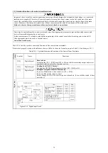
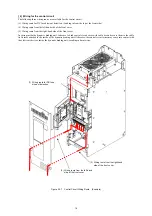
Page 18: ...er The front cover fixing points have double circle holes that allow the front cover to be removed without removing the screws 2 Hold the handles and slide the cover up and towards you 3 Mount the front cover in the reverse order of removal 4 To show the control circuit terminals on the control printed circuit board open the keypad enclosure left hand door Keypad enclosure Screws Front cover Screw...

Page 19: ...w specifications and recommended wire sizes main circuit terminals This section provides information on choices of wire sizes for main circuit Depending upon the main circuit wiring electric noise could be applied to the control circuit causing malfunctions Refer to the FRENIC VG User s Manual Stack type Chapter 7 EMC Compatible Peripherals Appendix 5 Proficient Way to User Inverters on Electric N...

Page 20: ...ctors U1 and U2 For details refer to Section 2 2 7 DCF1 DCF2 Inputs for fuse blowout detection Terminals for detecting a blowout of the DC fuse When the circuit between terminals DCF1 and DCF2 is OFF the dynamic breaking unit can detect the blowout of the DC fuse To use the detection function remove the short bar from these terminals to close the microswitch of the DC fuse 24 VDC 12 mA typ Main ci...

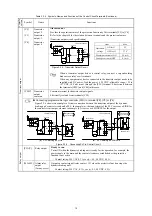
Page 21: ...ternal timers An accident could occur Table 2 2 4 lists the symbols names and functions of the control circuit terminals Route wires properly to reduce the influence of noise Refer to the notes for analog input in Table 2 2 4 and chapter 2 2 1 Table 2 2 4 Symbols Names and Functions of the Control Circuit Terminals Classifi cation Symbol Name Functions X2 Digital input 2 Reset alarm Switching the ...

Page 22: ...OURCE Figure 2 2 3 Circuit Configuration Using a Relay Contact Digital input Using a programmable logic controller PLC to turn X2 to X7 ON or OFF Figure 2 2 4 shows two examples of a circuit configuration that uses a programmable logic controller PLC to turn control signal input X2 to X7 ON or OFF In circuit a the slide switch is turned to SINK factory default whereas in circuit b it is turned to ...

Page 23: ...for transistor output signals Electrically isolated from terminals CM Connecting programmable logic controller PLC to terminal Y2 Y3 or Y4 Figure 2 2 6 shows two examples of circuit connection between the transistor output of the dynamic braking unit s control circuit and a PLC In example a the input circuit of the PLC serves as a SINK for the control circuit output whereas in example b it serves ...

Page 24: ...he dynamic braking unit take care to bind control circuit wires with cable ties and secure them to the cable tie fixtures attached to the inside of the dynamic braking unit Otherwise the control circuit wires may come into contact with the electronic devices inside the dynamic braking unit resulting in burnt wires Figure 2 2 7 Control Circuit Wiring Route Example 1 Wiring route for DC fuse blowout...

Page 25: ... prevent the wires from coming into contact with those components be sure to secure the wires to the cable tie fixtures using cable ties Otherwise those components in contact with the wires may come off due to vibration In wiring take care not to stretch the wires too tight Connection terminal for fuse blowout detection Wiring route Cable tie fixtures Rank 4 Figure 2 2 8 Wiring Route for DC Fuse B...

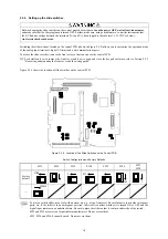
Page 26: ...o remove the front cover and how to open and close the keypad enclosure refer to Section 2 2 2 Removing and mounting the front cover and the wiring guide Figure 2 2 9 shows the location of slide switches on the control PCB SW5 SW1 SW6 SW8 SW7 SW3 SW4 SW2 Figure 2 2 9 Location of the Slide Switches on the Control PCB Switch Configuration and Factory Defaults 18 SW1 SW2 SW3 SW4 SW5 SW6 SW7 SW8 Facto...

Page 27: ...ove the connector from the U1 to U2 position In any other cases retain the connector in the U1 position factory default Terminal rating 660 to 690 VAC 50 60 Hz Maximum current 1 0 A 575 to 600 VAC 50 60 Hz Maximum current 1 0 A Auxiliary power printed circuit board Figure 2 2 10 Inserting Removing the connector To remove the connector pinch its upper side between your fingers unlock its fastener a...

Page 28: ...use the inter dynamic breaking unit communications link error to generate an alarm Use the supplied optical fiber cable to connect the dynamic breaking unit and the high speed serial communication capable terminal block Note that the colors of the plugs at the ends of the cable are different light gray and dark gray Be sure to match the colors of the plug and connector when connecting them Connect...

Page 29: ...Protective Functions The dynamic breaking unit has various protective functions to prevent the system from going down and reduce system downtime If any problem arises follow the procedures given in Section 4 2 and onwards for troubleshooting 4 2 Before Proceeding with Troubleshooting If any of the protective functions has been activated first remove the cause Then after checking that the all run c...

Page 30: ...at sink that cools down the IGBTs increases due to stopped cooling fans 8 Dynamic breaking unit internal overheat This function is activated if the temperature surrounding the control printed circuit board increases due to poor ventilation inside the dynamic breaking unit ON ON OFF 9 Inter dynamic breaking unit communicatio ns link error This function is activated if a communications error occurs ...

Page 31: ...ck and Suggested Measures 1 When attaching a DC fuse on input section of the dynamic breaking unit connect b contact of microswitch provided for attachment to DC fuse to input terminals DC1 DCF2 for detecting open fuse 2 If the fuse has blown the internal elements may be broken NEVER turn the power ON to prevent the secondary damage Contact your Fuji Electric representative 1 The fuse blew due to ...

Page 32: ...ynamic breaking unit Lower the temperature around the dynamic breaking unit e g ventilate the cabinet where the dynamic breaking unit is mounted Check if there is sufficient clearance around the dynamic breaking unit Change the mounting place to ensure the clearance 2 Ventilation path is blocked Check if the heat sink is not clogged Clean the heat sink For the cleaning procedure contact your Fuji ...

Page 33: ...terval of cooling fans refer to Section 5 4 List of Periodic Replacement Parts The replacement intervals are based on the stack type s service life estimated at an ambient temperature of 30 C In environments with an ambient temperature above 40 C or a large amount of dust or dirt the replacement intervals may be shorter Standard replacement intervals mentioned above are only a guide for replacemen...

Page 34: ...iscoloration cracks and swelling of the casing 2 Check that the safety valve does not protrude remarkably 1 2 Visual inspection 1 2 No abnormalities Control circuit Printed circuit board 1 Check for loose screws and connectors 2 Check for odor and discoloration 3 Check for cracks breakage deformation and remarkable rust 4 Check the capacitors for electrolyte leaks and deformation 1 Retighten 2 Olf...

Page 35: ...here you purchased the product or your nearest Fuji Electric representative 5 5 Insulation Test Since the dynamic breaking unit has undergone an insulation test before shipment avoid making a Megger test at the customer s site If a Megger test is unavoidable for the main circuit observe the following instructions otherwise the dynamic breaking unit may be damaged A withstand voltage test may also ...

Page 36: ... by Fuji Electric s Service Department is 6 months from the date that repairs are completed 2 Warranty range 1 In the event that breakdown occurs during the product s warranty period which is the responsibility of Fuji Electric Fuji Electric will replace or repair the part of the product that has broken down free of charge at the place where the product was purchased or where it was delivered Howe...

Page 37: ...ts even within this 7 year period For details please confirm at our company s business office or our service office 4 Transfer rights In the case of standard products which do not include settings or adjustments in an application program the products shall be transported to and transferred to the customer and this company shall not be responsible for local adjustments or trial operation 5 Service ...

Page 38: ...formation in handling setting up and operating of the FRENIC VG series of inverters Please feel free to send your comments regarding any errors or omissions you may have found or any suggestions you may have for generally improving the manual In no event will Fuji Electric Co Ltd be liable for any direct or indirect damages resulting from the application of the information in this manual ...

Page 39: ...Fuji Electric Co Ltd Gate City Ohsaki East Tower 11 2 Osaki 1 chome Shinagawa ku Tokyo 141 0032 Japan Phone 81 3 5435 7058 Fax 81 3 5435 7420 URL http www fujielectric com 2014 3 ...

Reviews: