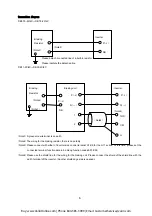
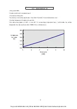
Connection diagram
DB0.75-2C/4C
~
DB7.5-2C/4C
6
Inver
(
Note2
)
(
Note1
)
Please detach connected line of a built-in resistor.
Please insulate the detached line.
ter
Braking
Resistor
P
(+)
DB
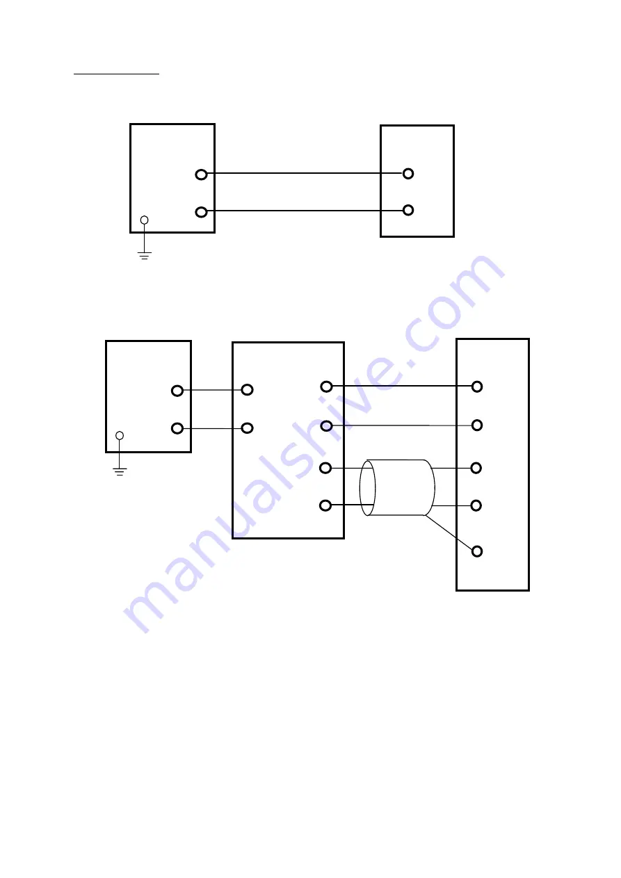
DB11-2C/4C
~
DB22-2C/4C
(
Note1
)
A green screw terminal is an earth.
(
Note2
)
The wiring for the braking resistor, there is no polarity.
(
Note3
)
Please connect with either of inverter side control terminal X1-X9 for the G11 series. At this time, please set the
connected terminal function data in 9 among function codes E01-E09.
Inverter
Braking
Resisto
r
DB
(
Note3
)
(
Note2
)
(
Note1
)
P
(+)
Braking unit
(
Note4
)
P
(+)
N
(-)
THR
CM
G
1
2
P
(+)
N
(-)
(
Note4
)
Please use the shield line for the wiring for the braking unit. Please connect the shield of the shield line with the
earth terminal of the inverter. (Another shield edge side is opened.)
Buy: www.ValinOnline.com | Phone 844-385-3099 | Email: CustomerService@valin.com


