5-40
This function provides a tentative information for service life of the parts. If this
signal is issued, check the service life of these parts in your system according to the
maintenance procedure to determine whether the parts should be replaced or not.
To maintain stable and reliable operation and avoid unexpected failures, daily and
periodic maintenance must be performed.
For details, refer to Chapter 7, Section 7.2, Table 7.2 "Replacement Parts
Judgement with Menu #5 "Maintenance Information" as a Guide."
Inverter
output
on--
RUN2
(Function code data = 35)
㩷
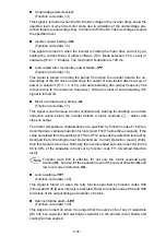
This signal is turned on when the motor is driven by the frequency higher than the
starting frequency or DC braking is activated.
Overload prevention control--
OLP
(Function code data = 36)
㩷
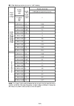
This signal is turned on when the overload prevention function is activated if the
frequency drop rate comes to be the setting specified by function code H70. The
minimum ON-duration is 100 ms.
For details of the overload prevention control, refer to the descriptions of
function code H70.
Current
detected--
ID
(Function code data = 37)
㩷
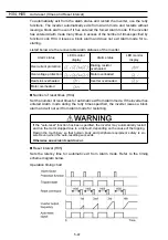
This signal is turned on when the output current exceeds the operation level set by
Overload Early Warning/Current Detection/Low Current Detection (E34: Level) for a
duration longer than specified by Current Detection/Low Current Detection (E35:
Timer). The minimum ON-duration is 100 ms.
Function codes E34 and E35 are used not only to set the current detection
ID
, but also to set the operation level of the motor overload early warning
OL
and low current detection
IDL
and the timer count.
Low level current detected--
IDL
(Function code data = 41)
㩷
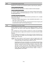
This signal is turned on when the output current drops below the operation level set
by Overload Early Warning/Current Detection/Low Current Detection (E34: Level)
for a duration longer than specified by Current Detection/Low Current Detection
(E35: Timer). The minimum turning-ON time is 100 ms.
Function codes E34 and E35 are used not only to set the low current
detection
IDL
, but also to set the operation level of the overload early
warning
OL
and current detection
ID
and the timer count.
Alarm output (for any fault)--
ALM
(Function code data = 99)
㩷
This signal is turned on if the protection function is activated so that the inverter
enters Alarm mode.
Summary of Contents for Frenic Mini FRN001C1E-2U
Page 85: ...5 4 ...
Page 88: ...5 7 ...
Page 89: ...5 8 C codes Control Functions of Frequency ...
Page 92: ...5 11 J codes Application Functions y codes Link Functions ...
Page 167: ...8 6 8 3 Common Specifications ...
Page 168: ...8 7 ...
Page 171: ...8 10 8 5 External Dimensions 8 5 1 Standard models ...
Page 172: ...8 11 ...
Page 173: ...8 12 8 5 2 Models available on order EMC filter built in type ...
Page 174: ...8 13 ...
Page 192: ...MEMO ...
Page 193: ...MEMO ...
Page 194: ...MEMO ...
Page 196: ...Fuji Electric FA Components Systems Co Ltd Fuji Electric Corp of America 2007 06 F07 F07 00CM ...


