3-5
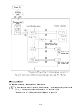
Figure 3.3 shows the procedure for selecting the desired monitor item and the sub-item for speed
monitoring.
*1 The speed monitor displays the output frequency (Hz), reference frequency (Hz), load shaft speed (r/min),
line speed (m/min.), or constant rate of feeding time (min.), depending on the setting of function code
E48.
*2 The PID-related information will appear only when the inverter is under PID control. When PID control is
not in effect (J01 = 0) while data of the function code E43 is 10 or 12, or immediately after power on, "– –
– –" will be displayed.
*3 This will appear only when timer operation is enabled by function code C21. When timer operation is not
in effect (C21 = 0) while data of the function code E43 is 13, or immediately after power on, "– – – –" will
be displayed.
Figure 3.3 Selecting Monitor Item and Speed Monitor Sub-item
Summary of Contents for Frenic Mini FRN001C1E-2U
Page 85: ...5 4 ...
Page 88: ...5 7 ...
Page 89: ...5 8 C codes Control Functions of Frequency ...
Page 92: ...5 11 J codes Application Functions y codes Link Functions ...
Page 167: ...8 6 8 3 Common Specifications ...
Page 168: ...8 7 ...
Page 171: ...8 10 8 5 External Dimensions 8 5 1 Standard models ...
Page 172: ...8 11 ...
Page 173: ...8 12 8 5 2 Models available on order EMC filter built in type ...
Page 174: ...8 13 ...
Page 192: ...MEMO ...
Page 193: ...MEMO ...
Page 194: ...MEMO ...
Page 196: ...Fuji Electric FA Components Systems Co Ltd Fuji Electric Corp of America 2007 06 F07 F07 00CM ...


