6-2
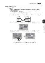
1.
Error
Messages
2.
Data Loading
If an error is detected on the screen data in the RUN mode, the following messages are displayed on
the TS series.
Error Messages
Contents
Solution
Error code received
An error code was sent by a controller.
(NAK)
Examine the controller error code and solve
the problem.
Break
The controller’s SD remains at the low level.
Examine the connection between the
controller’s SD and the TS’s RD.
Invalid memory
(Mitsubishi CPU)
You specified an address that exceeds the
memory range of the PLC that you are linked
to.
Check the type and range of memory that you
set.
Format
The code of the received data is invalid.
1.
Confirm link unit settings.
(After making settings, cut power to the
controller.)
2.
On the V-SFT-5 editor, select [System
Setting]
→
[Device Connection Setting]
and check the settings.
3.
If errors only occur from time to time, a
noise-based communication error may be
present.
Compare
(HIDIC S10)
Transmission data and received data are
different.
NAK
A NAK code is received.
Transaction Error
(Allen-Bradley PLC)
Transmitted transaction data and received
transaction data are not in agreement.
Communication Error
An unclear communication error is detected.
Count error
(Mitsubishi CPU and Q link
unit)
The expected data amount is different from the
count value.
Command error
(Mitsubishi CPU and Q link
unit)
The response code differs from the expected
code.
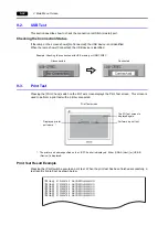
&CVC.QCFKPI
'TTQT
6JG54#/CTGCKUPQVHQTOCVVGF
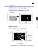
Screen No. Error
Error : XX (XX : XXX)
Error Messages
Contents
Solution
Screen No. Error
There is no setting for the
received screen.
At the start of communications, the TS series regards the value
in the read area “n + 2” as the screen number.
Check that this value is an existing screen number on the
controller.
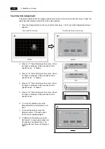
Error : XX (XX : XXX)
There is an error in the
created screen data.
According to the item number and the sub-item number
displayed on the TS series, find the edited screen where the
error occurs. Check the contents of the error (error number)
and remove the error.
For details on the item number and sub-item number, refer to
the TS Series Reference Manual.
Error : XX (XX : XXX)
Sub-item No.
Item No.
Error No.
Summary of Contents for MONITOUCH TS Series
Page 1: ......
Page 10: ...11 Features 2 Models and Peripheral Equipment 3 System Composition Product Outline ...
Page 43: ...2 26 6 LAN Connector TS1100i TS1070i Only Please use this page freely ...
Page 44: ...31 Mounting Procedure 2 Power Supply Cable Connection Installation ...
Page 49: ...41 Coin type Lithium Battery 2 DIP Switches Handling of TS Series Components ...
Page 57: ...4 8 2 DIP Switches Please use this page freely ...
Page 58: ...51 Before Operation 2 Main Menu Screen 3 System Menu TS Series Operations ...
Page 102: ...5 44 3 System Menu Please use this page freely ...
Page 103: ...61 Error Messages 2 Troubleshooting Error Handling ...
Page 110: ...71 Inspection and Maintenance 2 Warranty Policy Inspection and Maintenance ...
Page 114: ...7 4 2 Warranty Policy Please use this page freely ...

