50
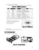
(2)Pin assignment of RS232C
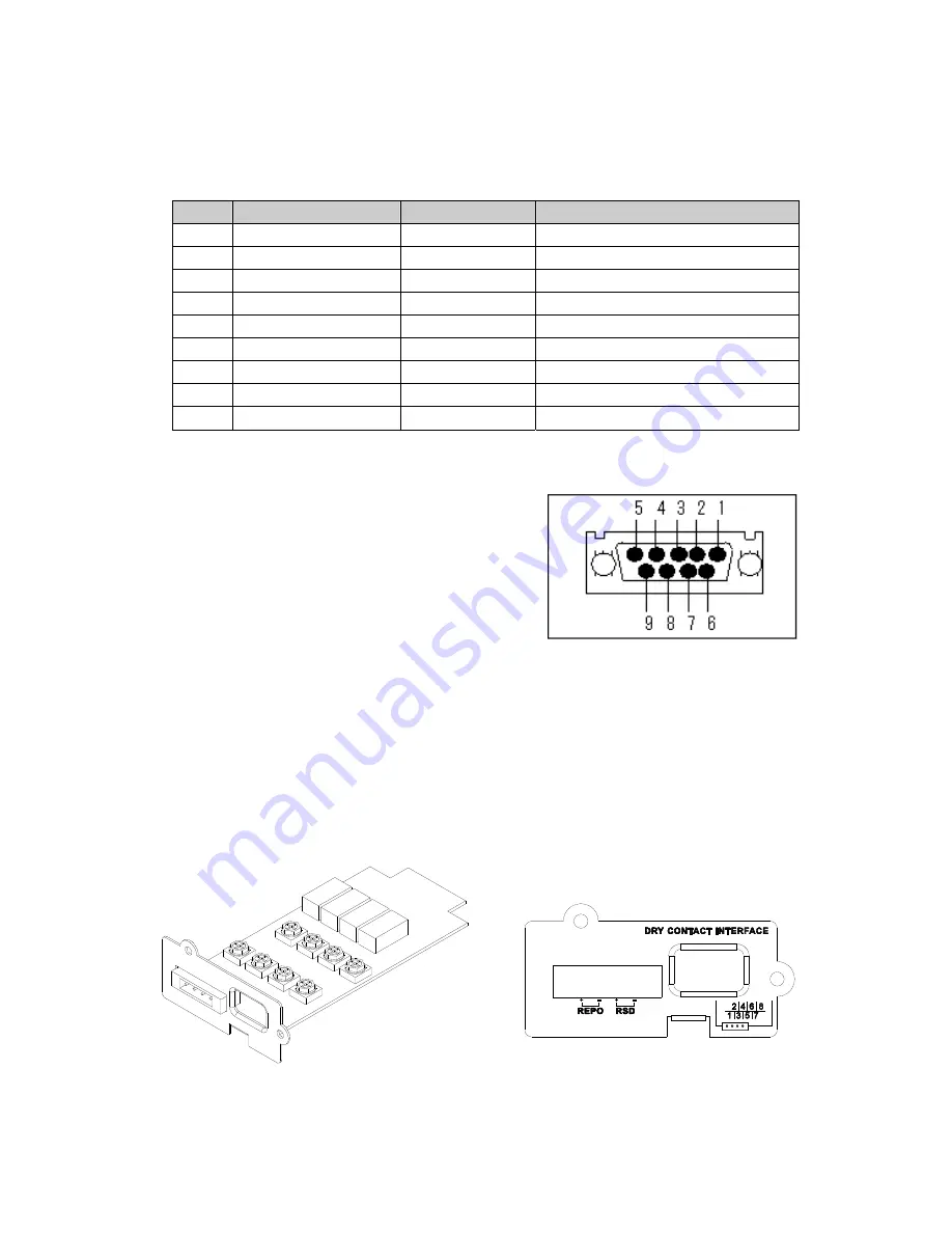
The pin assignment of RS232C (D-sub9P connector) is as follows.
Table 9-1 RS232C pin assignment
Pin
Singnal ※1)
Direction
Note
1
Low Battery
Reception
5V output
2
RxD
Reception
Reception signal
3
TxD
Transmission
Transmission signal
4
DTR
Transmission
DTR signal output
5
GND
――
GND
6
Alarm
Reception
5V output
7
RTS
Transmission
RTS signal output
8
UTL failure
Reception
5V output
9
RI
Reception
Wakeup on MODEM
※1) The network agent card is displayed for the DCE by the signal name that
sees from DTE (host terminal). The cable used is straight.
The RS232C port externals and
the pin layout (D-sub9P connector)
is shown in Figure 9-3.
※ Inch screw use
Figure 9-3 RS232C port
(3)Reset switch
This switch resets the network agent card.
9-2 Dry Contact Card
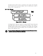
Externals are shown in Figure 9-4.
Figure 9-4 Dry Contact Card
Summary of Contents for PEN102J1C
Page 8: ...1 1kVA 1 5kVA VII...
Page 9: ...VIII 2 4kVA...
Page 10: ...3kVA IX...
Page 11: ...Tower Type The attention label becomes it as follows 1kVA X...
Page 19: ......
Page 27: ...8 Figure 1 Need Space...
Page 84: ......
Page 85: ......

