52
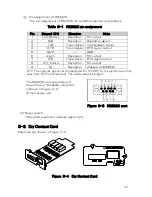
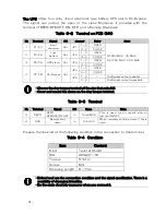
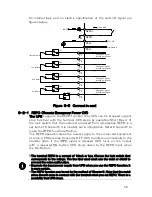
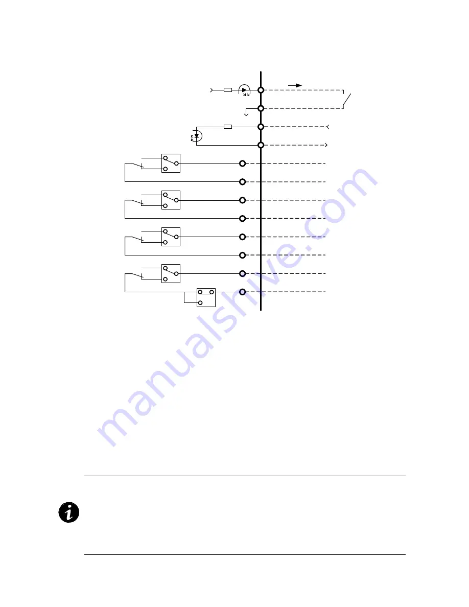
An internal logic and an electric specification of the card I/O signal are
figures below.
Figure 9-5 Connect in card
9-2-1 REPO(Remote Emergency Power Off)
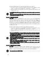
The UPS supports the REPO function that UPS can be stopped (urgent
stop function) with the terminal. UPS stops by operation(Short/Open) of
the lock switch that the customer prepared from remoteness. REPO is a
set item of Chapter6. It is invalidly set in initialization. Refer Chapter6 to
make the REPO function effective.
The REPO operation stops the power supply to the connected equipment
at once. UPS becomes Converter OFF. UPS transfers automatically to the
standby state, if the REPO signal is released. UPS turns on the output
with a repeated ON button. UPS shuts down by the REPO input when
the On-Battery.
・The terminal REPO is a current of 10mA or less. Choose the lock switch that
corresponds to the ratings. The line kind used must use the twist or shield to
prevent the noise malfunction.
・Separate the input power supply from UPS when you use the REPO function. It
is more certain..
・The REPO function can be set by the method of Chapter6. Note that the metal
piece doesn't come in contact with the terminal when you set REPO. There is a
possibility that UPS stops.
P1
P2
P3
P4
P5
P6
P7
P8
REPO+
REPO-
RSD+
RSD-
ISO12V
GND
10mA MAX
External GND
DC5~30V
3
2
JP1
3
2
JP2
3
2
JP3
JP4
1
1
3
2
1
Low Battery
On Bypass
Input Abnormal
UPS Alarm
DC30Vmax 2Amax
AC125Vmax 0.5Amax
DC30Vmax 2Amax
AC125Vmax 0.5Amax
DC30Vmax 2Amax
AC125Vmax 0.5Amax
DC30Vmax 2Amax
AC125Vmax 0.5Amax
2
1
3
JP5
1
Summary of Contents for PEN102J1C
Page 8: ...1 1kVA 1 5kVA VII...
Page 9: ...VIII 2 4kVA...
Page 10: ...3kVA IX...
Page 11: ...Tower Type The attention label becomes it as follows 1kVA X...
Page 19: ......
Page 27: ...8 Figure 1 Need Space...
Page 84: ......
Page 85: ......

