


– 15 –
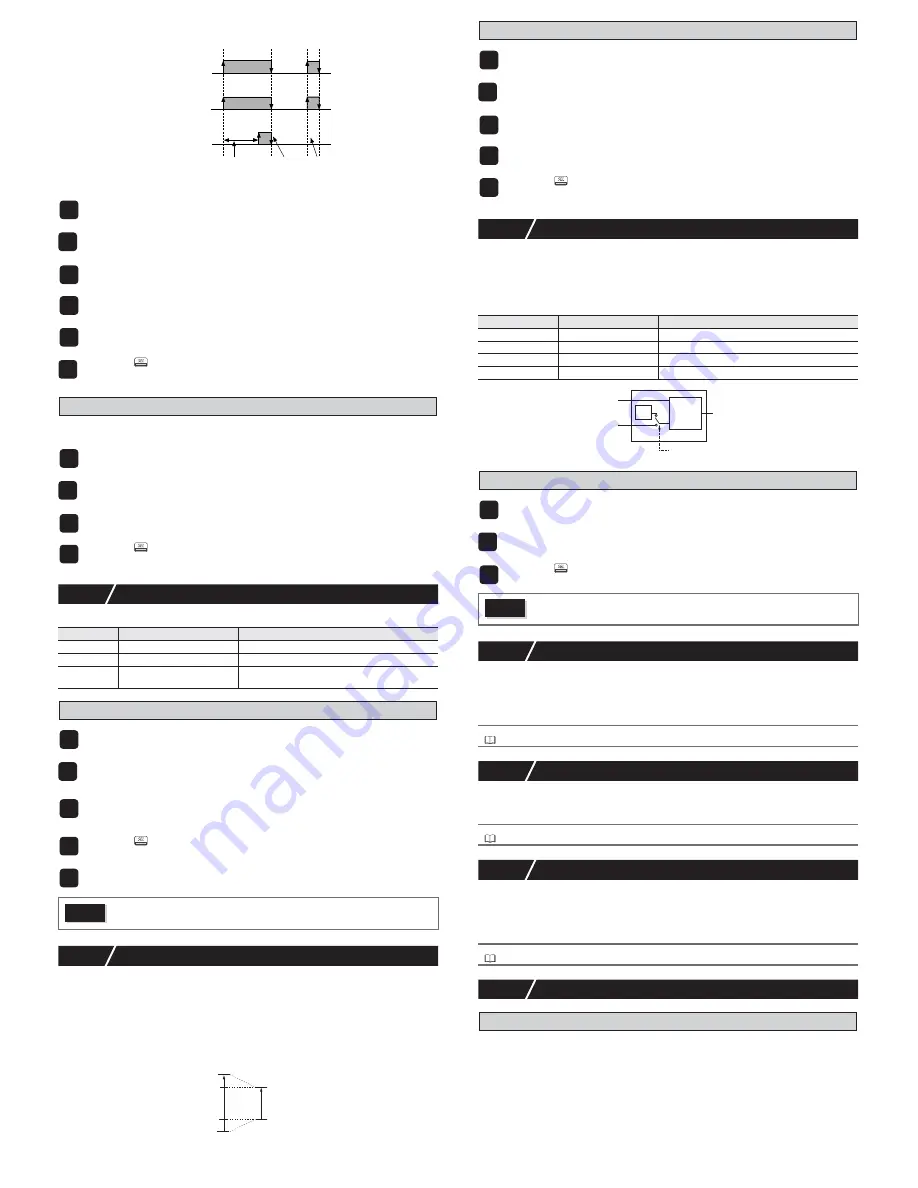
This is called a delay function because there is a delay between the event and outputting to
DO.
Use the following steps to set an alarm delay and hysteresis.
4. Setting the operation menu
Sets the alarm value so that DO is used as the alarm output.
Use the following steps to set this function.
7-13
Communication Functions
Set the following to communicate with the host.
Setting communication functions
7-14
Re-transmission Output Function
The re-transmission output function delivers an analog output signal from the controller.
The following values can be output:
PV, SV, MV, DV (PV-SV), PFB
Depending on the type of output, you can choose the voltage type or current type.
The re-transmission output also contains a scaling function.
The following example shows a re-transmission output of 100% when PV=960°C (80% FS)
and a re-transmission output of 0% when PV=240°C (0% FS) for a PV range of 0 to 1200°C.
Setting re-transmission output function
7-15
Remote SV Function
The remote SV function controls the analog input signal coming into the controller as SV.
The input terminal becomes RSV1 or RSV2.
The remote SV function contains a zero/span adjustment function, as well as an input filter
function.
The setup menu ("
SET [h
6
") must be set in the following manner before using the remote SV
function.
Switching to remote SV operation
7-16
Heater Break Alarm Functions
The heater wiring passes through the CT, allowing the current value to be monitored and
detect errors in the heater line.
Heater break are detected by drops in the heater current. Setting the detection values acti-
vates this function.
•
Related parameters: “
hb1
”, “
hb1h
” (“
ALM Ch 8
”), “
Ct1
”,“
LC1
” (“
Mon Ch 5
”)
7-17
Loop Break Alarm
Detects when the control loop is open (break) without using the CT, but instead observing the
control output and PV.
•
Related parameters: “
LbTM
”, “
TbAb
” (“
ALM Ch8
”)
7-18
Load Short-circuit Alarm
The heater wiring passes through the CT, allowing the current value to be monitored and
detect errors in the heater line.
The load short-circuit is detected by drops in the heater current. Setting the detection values
activates this function.
•
Related parameters: "
hS1
", "
hS1h
" ("
ALM Ch8
")
7-19
Other Functions
1. Soft start function
When turning on the equipment (including the temperature controller), the soft start function
suppresses the MV to become maximum output. It places an upper limit on MV output for a
specified amount of time after power is turned on.
This function is useful for effects such as suppressing the heater output during equipment star-
tup, and makes load lightened.
After the specified time has passed after switching on the equipment (or if SFTM = 0), the soft
start function ends and normal controls begin.
1
Display the alarm menu ("
ALM Ch 8
").
2
Display hysteresis 1 ("
A1hY
") and set the hysteresis.
3
Display delay time 1 ("
dLY1
") and set the delay.
4
Display delay time units 1 ("
dL1U
") and set the units to minutes or seconds.
5
Set the values for alarm 2 to alarm 5 as necessary.
6
Press the
key to set the value.
1
Display the operation menu ("
oPE Ch1
").
2
Set the alarm 1 set value ("
AL1
") or "
AL1L
" and "
AL1H
".
The parameters displayed will vary according to the type of alarm.
3
Set up to alarm 5 as necessary.
4
Press the
key to set the value.
Display
Parameter
Function
"
STno
"
ST No. setting
Sets the station number.
"
[oM
"
Parity/baud rate setting
Choose the configuration of parity and baud rate
"
S[[
"
Setting communication
permissions
Set whether or not the host has permission to
overwrite.
1
Display the communication menu ("
[oM [h 9
").
2
Display ST No. setting parameter ("
Stno
") and choose 1, and then display Par-
ity/baud rate setting parameter (“
CoM
”) and choose 9600 bps, even ("
96ev
").
This sets the baud rate to 9600 bps and the parity to "even".
3
Display communication permissions ("
S[[
") and choose to allow read and over-
write permissions ("
rw
").
This sets the host to be allowed to read and overwrite the controller.
4
Press the
key to set the value.
5
Turn the controller off and on again.
Caution
The communication function settings will not be active until the power for the
controller is turned OFF/ON.
ON
OFF
ON
OFF
ON
OFF
ON delay
set time
alarm
normal
alarm relay
relay with
ON delay
cancel
no relay output
(alarm during delay is invalid)
(Ex.) Alarm On Delay
Function
20% (AoL)
re-transmission output
calculation value
actual re-transmission
output
100
°
C
0%
80% (AoH)
upper/lower limit
scaling range
100%
0%
1
Display the setup menu ("
SET [h
6
").
2
Display the AO output function parameter ("
Aot
") and choose the PV.
This selects PV as the re-transmission output.
3
Display AO lower limit scaling ("
AoL
") and set the lower limit scaling (in this
example, set it to 20%).
4
Display AO upper limit scaling ("
AoH
") and set the upper limit scaling (in this
example, set it to 80%).
5
Press the
key to set the value.
Display
Parameter
Function
"
rEMO
" (rEMO)
RSV Zero adjustment
Adjusts the zero of the RSV input
"
rEMS
" (rEMS)
RSV Span adjustment
Adjusts the span of the RSV input
"
rEMr
" (rEMr)
RSV input range
Sets the range for RSV input
"
rTF
" (rTF)
RSV input filter
Sets the time constant for the RSV input filter
1
Display the operation menu ("
oPE [h 1
").
2
Display the switching to remote SV parameter ("
rEm
") and choose remote
("
rEM
").
3
Press the
key to set the value.
Caution
•
Soft start is not displayed during the remote SV operation.
•
Do not use remote SV and the SV selection function at the same time.
Refer to
For details on the heater break alarm, refer to the "Operation Manual".
Refer to
For details on the loop break alarm, refer to the "Operation Manual".
Refer to
For more details on the load short-circuit alarm, refer to the "Operation Manual"..
PV
PID
calculation
local
SV
remote SV
(DC0 to 5/1 to 5V)
control output
Switch to remote SV parameter rEM


