


– 8 –
6-5
Monitor (Ch5)
You can check the ramp soak progress, control output, heater current, remaining time, and
other status functions.
6-6
Setup (Ch6)
Sets up the input range, output range, and other items for the equipment.
6-7
System (Ch7)
Assigns the functions of the DI/DO, LED lamp, and other controls.
Parameter
display symbol
Parameter name
Function
Setting range
Remarks
"
StAt
" (STAT)
Ramp soak
progress
Displays the
progress of the
ramp soak
oFF (ramp soak stopped)
1-rP (ramp in step 1)
1-Sk (soak in step 1)
16rP (ramp in step 16)
16Sk (soak in step 16)
End (ramp soak finished)
"
Mv1
" (Mv1)
MV1
Displays the output
value of the control
output (OUT1)
-3.0 to 103.0%
"
Mv2
" (Mv2)
MV2
Displays the output
value of the control
output
(OUT2)(during dual
control)
-3.0 to 103.0%
(Note4)
"
PFb
" (PFb)
Displays the PFB
input value
Displays the input
value of the
position feedback
-3.0 to 103.0%
(Note8)
"
rSv
" (rSv)
RSV input value
display
Displays the input
value of the RSV
-5 to 105% FS
(Note1)
"
[t1
"
(CT1)
Heater current 1
Displays the current
through the CT
0, 0.4 to 50.0A
(Note10)
(Note13)
"
LC1
"
(LC1)
Leak current value
1
Displays the leak
current value of CT.
0, 0.4 to 50.0A
(Note 10)
(Note 13)
"
tm1
"
(TM1)
Remaining time on
timer 1
Displays the remaining
time on timer 1
0 to 9999 sec/ 0 to 9999min
(Note3)
"
tm5
"
(TM5)
Remaining time on
timer 5
Displays the remaining
time on timer 5
0 to 9999 sec/ 0 to 9999min
"
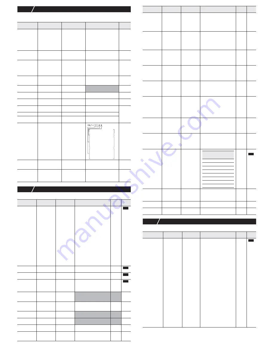
FALT
"
(FALT)
Error source
display
Displays the
source of an error
"
PLno
"
(
PLno
)
Current palette No.
Displays the PID
palette No.
currently selected.
0 to 7
"
PTno
"
(
PTno
)
Current pattern
No.
Displays the
pattern No. of the
ramp soak
currently selected.
0 to 6
Parameter
display symbol
Parameter name
Function
Setting range
Initial
value
Remarks
"
PvT
" (PvT)
PV input type
Sets the type
of input sensor
0 (no function)
1 (PT 100
Ω
)
2 (J)
3 (K)
4 (R)
5 (B)
6 (S)
7 (T)
8 (E)
9 (no function)
10(no function)
11 (no function)
12 (N)
13 (PL-
2
)
14 (no function)
15 (0 to 5V / 0 to 20mA)
16 (1 to 5V / 4 to 20mA)
17 (0 to 10V)
18 (2 to 10V)
19 (0 to 100mV)
3 (K)
"
Pvb
" (Pvb)
PV input lower
limit
Sets the lower
limit of PV input
-1999 to 9999
0
°
C
"
PvF
" (PvF)
PVinput upper
limit
Sets the upper
limit of PV input
-1999 to 9999
400
°
C
"
Pvd
" (Pvd)
Decimal point
position
Sets the number
of decimal point
positions for the
PV/SV
0 (No digit after decimal point)
1 (1 digit after decimal point)
2 (2 digit after decimal point)
0
"
PvoF
" (PvoF)
PV input shift
Sets the amount
of shift for PV
input
-10 to 10% FS
0%FS
"
tF
" (TF)
PV input filter
Sets the time
constant for the
PV input filter
0.0 to 120.0 sec
5.0 sec
"
rEm0
" (rEM0)
RSV Zero
adjustment
Adjusts the zero
RSV input
-50 to 50% FS
0%FS
(Note1)
"
rEmS
" (rEMS)
RSV Span
adjustment
Adjusts the
span RSV input
-50 to 50% FS
0%FS
(Note1)
"
rEmr
" (rEMr)
RSV input
range
Sets the range
for RSV input
0-5 (0 to 5V)
1-5 (1 to 5V)
1-5
(Note1)
"
rtF
" (rTF)
RSV input
filter
Sets the time
constant for the
RSV input filter
0.0 to 120.0 sec
0.0 sec
(Note1)
…
…
…
…
…
fixed at 0
8bit : PV input underflow
9bit : PV input overflow
10bit: underrange
11bit: overrange
12bit: RSV underrange
13bit: RSV overrange
14bit: range setting error
15bit: EEPROM error
0bit: PFB input underflow
1bit: PFB input overflow
RST
RST
RST
RST
"
[1r
" (C1r)
OUT1 range
Sets the range
of the control
output (OUT1)
0-5 (0 to 5V)
1-5 (1 to 5V)
0-10 (0 to 10V)
2-10 (2 to 10V)
0-20 (0 to 20mA)
4-20 (4 to 20mA)
0-10
(voltage
)
4-20
(current)
(Note9)
(Note14)
"
[2r
" (C2r)
OUT2 range
Sets the range
of the control
output (OUT2)
(Also sets for the
re-transmission
output)
0-5 (0 to 5V)
1-5 (1 to 5V)
0-10 (0 to 10V)
2-10 (2 to 10V)
0-20 (0 to 20mA)
4-20 (4 to 20mA)
0-10
(voltage
)
4-20
(current)
(Note12)
(Note14)
(Note18)
"
FLo1
" (FLo1)
Output 1 set
value during
FALT
Sets the output
value for the
control output
(OUT1) during
FALT
-3.0 to 103.0%
-3.0%
"
Flo2
" (FLo2)
Output 2 set
value during
FALT
Sets the output
value for the
control output
(OUT2) during
FALT
-3.0 to 103.0%
-3.0%
(Note4)
"
SFo1
" (SFo1)
Soft Start
output 1 set
value
Sets the output
value for the
control output
(OUT1) during
soft start
-3.0 to 103.0%
103.0%
"
SFtm
" (SFTM)
Soft Start set
time
Sets the time from
startup to the finish
of soft start
00:00 to 99:59 (hour:min)
0.00
(hour:
min)
Be
sure to
set
0.00
during
dual
control.
"
Sbo1
" (Sbo1)
OUT1 output
set value
during standby
Sets the output
value for the
control output
(OUT1) during
standby
-3.0 to 103.0%
-3.0%
"
Sbo2
"
(
Sbo2)
OUT2 output
set value
during standby
Sets the output
value for the
control output
(OUT2) during
standby
-3.0 to 103.0%
-3.0%
(Note4)
"
Sbmd
" (SbMd)
Standby mode
setting
Sets the alarm
output, re-
transmission
output, and
PV/SV display
during standby
0
(Note15)
"
Aot
" (AoT)
Types of AO
output
Displays the
types of re-
transmission
output
PV
SV
MV
DV
Pv
(Note12)
"
AoL
" (AoL)
AO lower limit
scaling
Sets the lower
limit of AO
-100 to 100%
0%
(Note12)
"
Aoh
" (Aoh)
AO upper limit
scaling
Sets the upper
limit of AO
-100 to 100%
100%
(Note12)
Parameter
display symbol
Parameter
name
Function
Setting range
Initial
value
Remarks
"
UkEy
" (UkEy)
Assigns the
USER key
Sets the
function of the
[USER] key
0 (no function)
1 (Switchover between STBY ON/OFF)
2 (Switchover between Auto/Manual)
3 (Switchover between Local/Remote)
4 (no function)
5 (Starts AT (standard))
6 (Starts AT (low PV))
7 (Ramp SV on/off)
8 (Ramp SV HOLD)
9 (Ramp soak OFF)
10 (Ramp soak RUN/HOLD)
11 (no function)
12 (Latch release (all))
13 (Latch release (DO1))
14 (Latch release (DO2))
15 (Latch release (DO3))
16 (Latch release (DO4))
17 (Latch release (DO5))
18 (Start timer (DO1))
19 (Start timer (DO2))
20 (Start timer (DO3))
21 (Start timer (DO4))
22 (Start timer (DO5))
23 (SV No. + 1 (send))
24 (PID No. + 1 (send))
25 (no function)
26 (Ra
mp soak
pattern No.
+ 1 (send))
27 (SV No. + 1,
PID No. + 1 (send))
2
Parameter
display symbol
Parameter name
Function
Setting range
Initial
value
Remarks
ALM
display/
output
Ao
outpu
t
PV/SV
displa
y
0 OFF
ON
ON
1 ON
ON
ON
2 OFF
OFF
ON
3 ON
OFF
ON
4 OFF
ON
OFF
5 ON
ON
OFF
6 OFF
OFF
OFF
7 ON
OFF
OFF
RST
RST


