background image

1

INZ-TN5ZBAS-E

The gas extractor is used to sample a gas from a funnel and send it to a gas analyzer.  As it is used under 

very severe conditions, it must provide the following performance.

•  Be usable at temperature of a sampling point.

•  Have no property to cause reaction with a sample gas or act as a catalyst on it.

•  Not be choked by dust, or easily replaceable or cleanable when choked.

•  Cause no remarkable sampling delay.

Fuji Electric offers gas extractors meeting these requirements on the basis of long-accumulated experience.

This gas extractor has a variety of types such as those with Y-shaped or T-shaped sampling tube depend

-

ing on the application, and therefore the actual product may differ slightly from the content of this manual 

depending on the customer’s required specification.

Please refer to the individually submitted manufacturing specifications for external drawings, specifications, 

accessories, spare parts, and consumable parts.

1.  outLinE

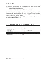
2.  ConFiRMAtion oF DELiVERED PRoDuCts

Delivered products list

Name of product

Quantity

Remark 

Gas extractor main unit

1


Sampling tube 

As specified length

Packing (for flange)


Bolt, nut, spring washer, plane washer (M16)

4 each 

When using standard flange JIS 10K50AFF

O-ring (G50, G65)

1 each

Summary of Contents for ZBAS

Page 1: ...Instruction Manual GAS EXTRACTOR High Dust Type TYPE ZBAS INZ TN5ZBAS E...

Page 2: ...ic will not bear any responsibility for a trouble caused by such a modification This instruction manual shall be stored by the person who actually uses the extractor After reading the manual be sure t...

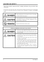
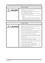
Page 3: ...tion on installation and transport of gas extractor DANGER This unit is not an explosion proof type Do not use it in a place with explosive gases to prevent explosion fire or other serious accidents C...

Page 4: ...c shocks or injury Before working take off wrist watch and other metallic objects to prevent electric shocks Wiring is allowed only when all power supplies are turned off This is required for preventi...

Page 5: ...a wet hand Otherwise you will have electric shocks When the inside of chimney or funnel is positive pressure and the extractor needs to be removed be careful with high temperature or hazardous gas as...

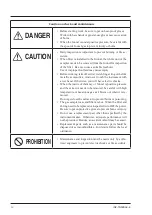
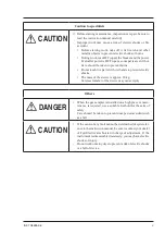
Page 6: ...ith wet hands to prevent electric shocks The mass of the device is approx 20 kg Careless transfer of the device may cause injury Others DANGER When the gas sampler is installed on a high place or main...

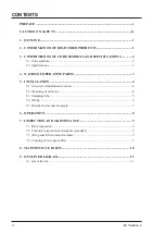
Page 7: ...G PARTS 3 5 INSTALLATION 4 5 1 Selection of installation location 4 5 2 Mounting of extractor 4 5 3 Sampling tube 5 5 4 Wiring 6 5 5 Blowback time chart example 7 6 OPERATION 8 7 INSPECTION AND MAINTE...

Page 8: ...ience This gas extractor has a variety of types such as those with Y shaped or T shaped sampling tube depend ing on the application and therefore the actual product may differ slightly from the conten...

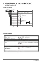
Page 9: ...sponse about 25 sec at 3L min Mass Approx 20 kg without sampling tube Sample gas outlet Rc1 2 Heater 100 V AC 400 W Installation Outdoor installation 3 CONFIRMATION OF CODE SYMBOLS AND SPECIFICATIONS...

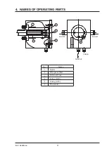
Page 10: ...3 INZ TN5ZBAS E 4 NAMES OF OPERATING PARTS 2 3 4 5 SAMPLE CABLE BLOW2 BLOW1 6 No Name Heater Wire gauze filter Terminal block O ring G50 O ring G65 Thermostat...

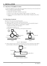
Page 11: ...nts 1 Sample gas temperature should be within the specified range 2 Mating flange that conforms to the limit of insertion angle of extractor should be prepared Also protective pipe and installatio n w...

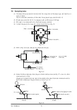
Page 12: ...on Blow 1 connection Fig 5 3 5 Refer to Fig 5 4 for an example for a blowback line pipe Sample Blow 1 Blow 2 Motorized valve 3 Motorized valve 2 Filter regulator Motorized valve 1 To analyzer sample l...

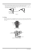
Page 13: ...led out side heating work will not be necessary Piping heating work Teflon tube in the heating pipe Extractor Heating pipe Fig 5 6 5 4 Wiring Open the gas extractor box and supply heater power of 100...

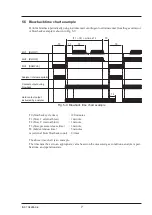
Page 14: ...spirator MV3 SAMPLE MV2 BLOW2 MV1 BLOW1 T0 T1 T2 T0 T4 T1 T2 m times T3 T3 Fig 5 9 Blowback time chart example T0 blowback cycle time 120 minutes T1 blow 1 external blow 1 minute T2 blow 2 internal bl...

Page 15: ...following points Preparation for operation Make sure that all the cables are connected correctly Turn ON the power Suck in the sample gas after the extractor is warmed up for about 1 hour While the f...

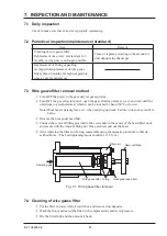
Page 16: ...ait until the unit drops to a temperature at which it can be touched by hand 50 C or lower Note Wear heat resistant gloves etc when carrying out work Failure to do so may result in burns Remove the he...

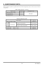
Page 17: ...1 year use Name of parts Quantity Arrangement code Wire gauze filter 10 m 1 ZBN5BS12 O ring JIS G50 1 O ring JIS G65 1 Table of maintenance parts Name of parts Code No Wire gauze filter 10 m ZBNS1112...

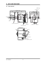
Page 18: ...BLOW2 BLOW1 BLOW2 FLANGE JIS10K50AFF CASE COVER FOR CABLE 2 A15c 2 A30a FOR SGP 15A PIPE 3 Rc1 2 INT THD THERMOSTAT CABLE GLANDS HEATER PIPE LOCK TERMINAL APPROX 177 CABLE SAMPLE SAMPLE 120 60 155 34...

Page 19: ...Gate City Ohsaki East Tower 11 2 Osaki 1 chome Shinagawa ku Tokyo 141 0032 Japan Phone 81 3 5435 7111 www fujielectric com www fujielectric com products instruments...

Reviews: