


SS1807-N002
Instruction of System
-
68/106
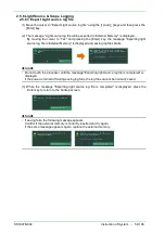
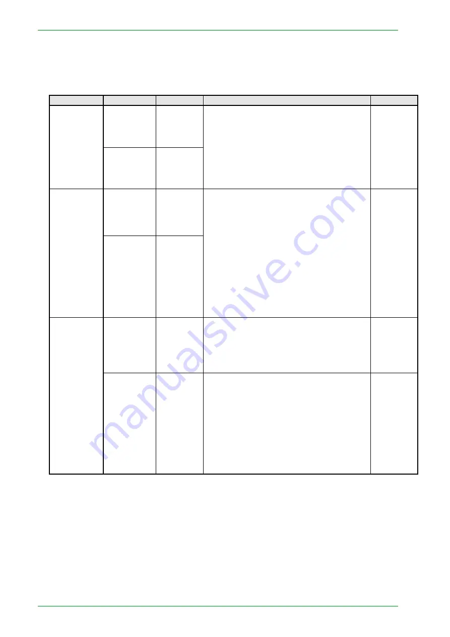
3.3.1.2 Printer Setup
In the displayed pop-up menu, select the desired setting using the [↑] and [↓] keys and then
press the [Enter] key to finalize the setting.
When manual data entry is required for an item, move the cursor to the item, press the [Enter]
key and then enter the desired value.
Menu item
Setting
Default
Description
Remarks
Connected
Printer
Not used
○
This setting is required when the color printer
(RS-232C system) or digital printer is used.
The model names of available printers are
displayed.
Select the printer used as the default printer
from the pop-up menu.
When "'Not used'" is selected, subsequent
settings are disabled and the model names
are not displayed in the user's menu.
UP-55MD
CP900D
UP-D25MD
Connecting
Port
RS232C-1
○
Select the port to which the printer is
connected.
[Note] When a pripheral device connected
with the RS-232C interface is
controlled from the processor
EP-6000, match the communicaiton
speed of the peripheral device with
the baud rate of the processor. If the
baud rate does not match, the
peripheral device does not function
normally.
For details on how to set the baud
rare. refer to the instruction manual
for each peripheral device.
RS232C-2
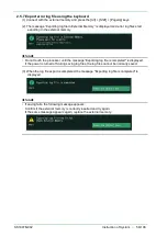
Print Mode
Auto
According to the setting of “Multi Print" in the
Printer Setup screen displayed from the
Peripheral Setup screen, when the specified
number of images is captured, printing is
performed automatically. The number of
prints is specified by the user.
Manual
○
Printing is performed by selecting the
desired images in the thumbnail display
screen.
[Note] In the case of the color printer
(RS·232C system). Image data is
overwritten each time an image is
captured.
Accordingly. to print the desired
image, press the Start
key on the keyboard immediatdy afrtr
capturing the image.
Summary of Contents for EP-6000
Page 1: ...Processor EP 6000 FV693A Service Manual SR1807 N002 Ver 1 Oct 2018 ...
Page 5: ...SS1807 N002 General Table of Contents 1 1 General Table of Contents ...
Page 13: ...SS1807 N002 Caution in Safety 1 12 Caution in Safety ...
Page 25: ...SS1807 N002 Product Specifications 1 11 Product Specifications ...
Page 36: ...SS1807 N002 Instruction of System 1 106 Instruction of System ...
Page 133: ...SS1807 N002 Instruction of System 98 106 ELC PCB Patient PCB APC PCB APC PCB APC PCB DC Pump ...
Page 139: ...SS1807 N002 Instruction of System 104 106 9 4 Outline of PCB roles ...
Page 142: ...SS1807 N002 Failure Analysis 1 64 Failure Analysis ...
Page 206: ...SS1807 N002 Checkup Replacement and Adjustment 1 137 Checkup Replacement and Adjustment ...
Page 343: ...SS1807 N002 Service Parts List 1 19 Service Parts List ...
Page 352: ...SS1807 N002 Service Parts List 10 19 2 2 2 4 1 3 3 2 3 3 6 5 ...
Page 356: ...SS1807 N002 Service Parts List 14 19 1 3 3 4 1 2 1 3 X 4 1 3 3 4 3 3 ...
Page 358: ...SS1807 N002 Service Parts List 16 19 3 1 2 1 ...
Page 360: ...SS1807 N002 Service Parts List 18 19 Fig 09 5 4 2 3 1 ...
Page 362: ...SS1807 N002 Periodical Maintenance 1 15 Periodical Maintenance ...
Page 377: ...SS1807 N002 Installation 1 68 Installation ...
Page 445: ...SS1807 N002 ...


