


SS1807-N002
Instruction of System
-
74/106
3.5.1 Card Information Setup
The setting of reading the information on magnetic cards on EP-6000 is made.
[NOTE] When the destination setting is other than Japan, this function is not supported.
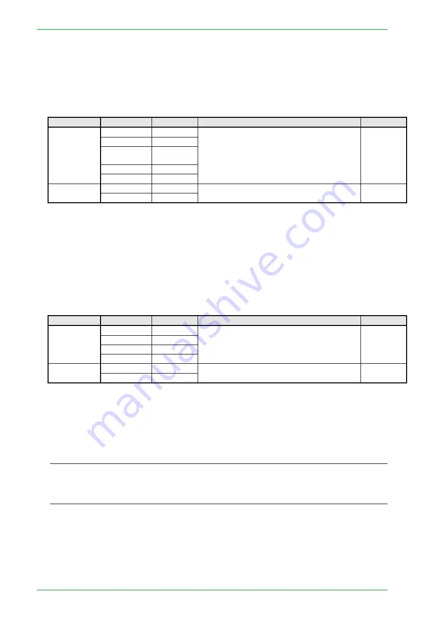
3.5.2 Device Setting 1
In the displayed pop-up menu, select the desired setting using the [↑] and [↓] keys and then
press the [Enter] key to finalize the setting.
Item
Setting
Default
Description
Remarks
Used
Not used
○
Select whether device being connected is
used or not.
When "Not used" is selected, the following
settings become unavailable.
DG-3000
DG-3000
(ID 16chars)
SU-1
SP-900
Connecting
port
RS232C-1
○
Set the connecting port of peripheral device.
RS232C-2
[NOTE] When a peripheral device connected with the RS-232C interface is controlled from the
processor EP-6000, match the communication speed of the peripheral device with the
baud rate of the processor.
If the baud rate does not match, the peripheral device does not function normally.
For details on how to set the baud rate, refer to the instruction manual for each
peripheral device.
3.5.3 Device Setting 2
In the displayed pop-up menu, select the desired setting using the [↑] and [↓] keys and then
press the [Enter] key to finalize the setting.
Item
Setting
Default
Description
Remarks
Used
Not used
○
Select whether device being connected is
used or not.
When "Not used" is selected, the following
settings become unavailable.
Bi-Direction
SU-1
SP-900
Connecting
port
RS232C-1
Set the connecting port of peripheral device.
RS232C-2
○
[NOTE] When a peripheral device connected with the RS-232C interface is controlled from the
processor EP-6000, match the communication speed of the peripheral device with the
baud rate of the processor.
If the baud rate does not match, the peripheral device does not function normally.
For details on how to set the baud rate, refer to the instruction manual for each
peripheral device.
◄ Reference ►
・
When [SU freeze/store] functions are assigned to the scope SW and the scope SW is pressed
while the ultrasonic device is turned off or not yet connected, a message is displayed as a
communication error.
・
DG and Bi-Direction are exclusively selected as a peripheral device.
Summary of Contents for EP-6000
Page 1: ...Processor EP 6000 FV693A Service Manual SR1807 N002 Ver 1 Oct 2018 ...
Page 5: ...SS1807 N002 General Table of Contents 1 1 General Table of Contents ...
Page 13: ...SS1807 N002 Caution in Safety 1 12 Caution in Safety ...
Page 25: ...SS1807 N002 Product Specifications 1 11 Product Specifications ...
Page 36: ...SS1807 N002 Instruction of System 1 106 Instruction of System ...
Page 133: ...SS1807 N002 Instruction of System 98 106 ELC PCB Patient PCB APC PCB APC PCB APC PCB DC Pump ...
Page 139: ...SS1807 N002 Instruction of System 104 106 9 4 Outline of PCB roles ...
Page 142: ...SS1807 N002 Failure Analysis 1 64 Failure Analysis ...
Page 206: ...SS1807 N002 Checkup Replacement and Adjustment 1 137 Checkup Replacement and Adjustment ...
Page 343: ...SS1807 N002 Service Parts List 1 19 Service Parts List ...
Page 352: ...SS1807 N002 Service Parts List 10 19 2 2 2 4 1 3 3 2 3 3 6 5 ...
Page 356: ...SS1807 N002 Service Parts List 14 19 1 3 3 4 1 2 1 3 X 4 1 3 3 4 3 3 ...
Page 358: ...SS1807 N002 Service Parts List 16 19 3 1 2 1 ...
Page 360: ...SS1807 N002 Service Parts List 18 19 Fig 09 5 4 2 3 1 ...
Page 362: ...SS1807 N002 Periodical Maintenance 1 15 Periodical Maintenance ...
Page 377: ...SS1807 N002 Installation 1 68 Installation ...
Page 445: ...SS1807 N002 ...


