SS1807-N002
Instruction of System
-
87/106
7.Setting of the Network
7.1 Outline
“Network function” of the EP-6000 means the function for transferring image data (files) to a
computer (server) using a standard file transfer method called FTP.
This function is called “FTP server” hereafter.
◆
Note
◆
EP-6000 supports 10BASE-T/100BASE-T.
Gigabit Ethernet such as 1000BASE-T is not supported.
If your network environment is Gigabit Ethernet, make a connection with a switching HUB etc.
supporting 10BASE-T/100BASE-T
• Only still images can be transferred and saved. Video images are not supported.
• Connecting to the existing network may affect the operation of other devices in the network.
Accordingly, consult your network administrator before connecting to the network.]
Each time the trigger (shutter) function is activated, an image file is transferred to the FTP
server.
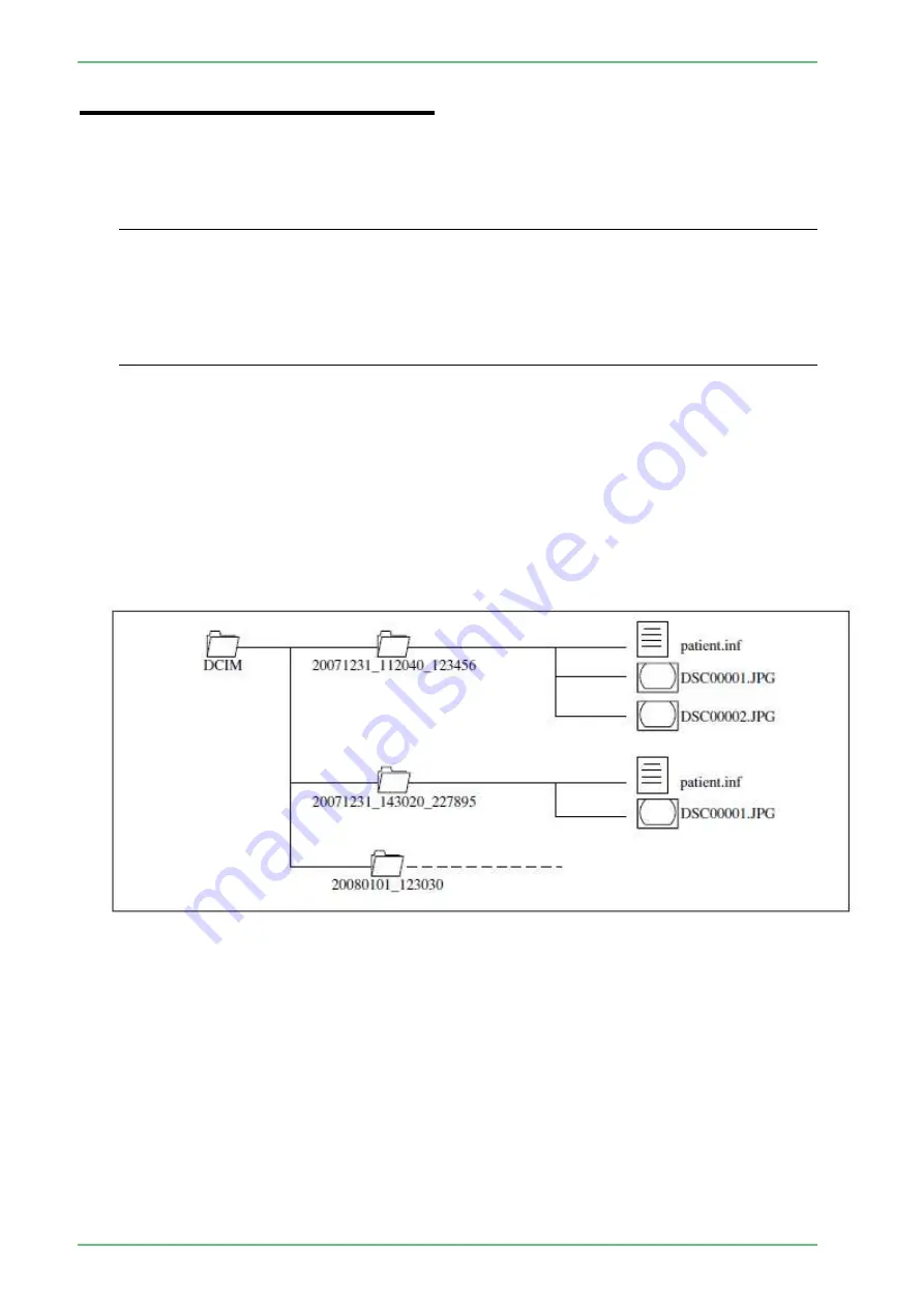
When an image is captured, a DCIM folder is created in the FTP server and a folder named
“Date_Time_Patient ID (or Examination Number)” is also created in the DCIM folder.
The patient information file “patient.inf” and image data are saved in the folder.
(Example: When the patient ID is “123456” and shooting starts at 11:20:40 a.m. on December
31st 2007, data is saved in the “¥DCIM¥20071231_112040_123456¥” folder.)
[Note] If patient information is not called up at the time of capturing the image, or if the patient ID
is not registered in patient information, a folder named “Date_Time” is created.
Summary of Contents for EP-6000
Page 1: ...Processor EP 6000 FV693A Service Manual SR1807 N002 Ver 1 Oct 2018 ...
Page 5: ...SS1807 N002 General Table of Contents 1 1 General Table of Contents ...
Page 13: ...SS1807 N002 Caution in Safety 1 12 Caution in Safety ...
Page 25: ...SS1807 N002 Product Specifications 1 11 Product Specifications ...
Page 36: ...SS1807 N002 Instruction of System 1 106 Instruction of System ...
Page 133: ...SS1807 N002 Instruction of System 98 106 ELC PCB Patient PCB APC PCB APC PCB APC PCB DC Pump ...
Page 139: ...SS1807 N002 Instruction of System 104 106 9 4 Outline of PCB roles ...
Page 142: ...SS1807 N002 Failure Analysis 1 64 Failure Analysis ...
Page 206: ...SS1807 N002 Checkup Replacement and Adjustment 1 137 Checkup Replacement and Adjustment ...
Page 343: ...SS1807 N002 Service Parts List 1 19 Service Parts List ...
Page 352: ...SS1807 N002 Service Parts List 10 19 2 2 2 4 1 3 3 2 3 3 6 5 ...
Page 356: ...SS1807 N002 Service Parts List 14 19 1 3 3 4 1 2 1 3 X 4 1 3 3 4 3 3 ...
Page 358: ...SS1807 N002 Service Parts List 16 19 3 1 2 1 ...
Page 360: ...SS1807 N002 Service Parts List 18 19 Fig 09 5 4 2 3 1 ...
Page 362: ...SS1807 N002 Periodical Maintenance 1 15 Periodical Maintenance ...
Page 377: ...SS1807 N002 Installation 1 68 Installation ...
Page 445: ...SS1807 N002 ...


