


SS1807-N002
Instruction of System
-
100/106
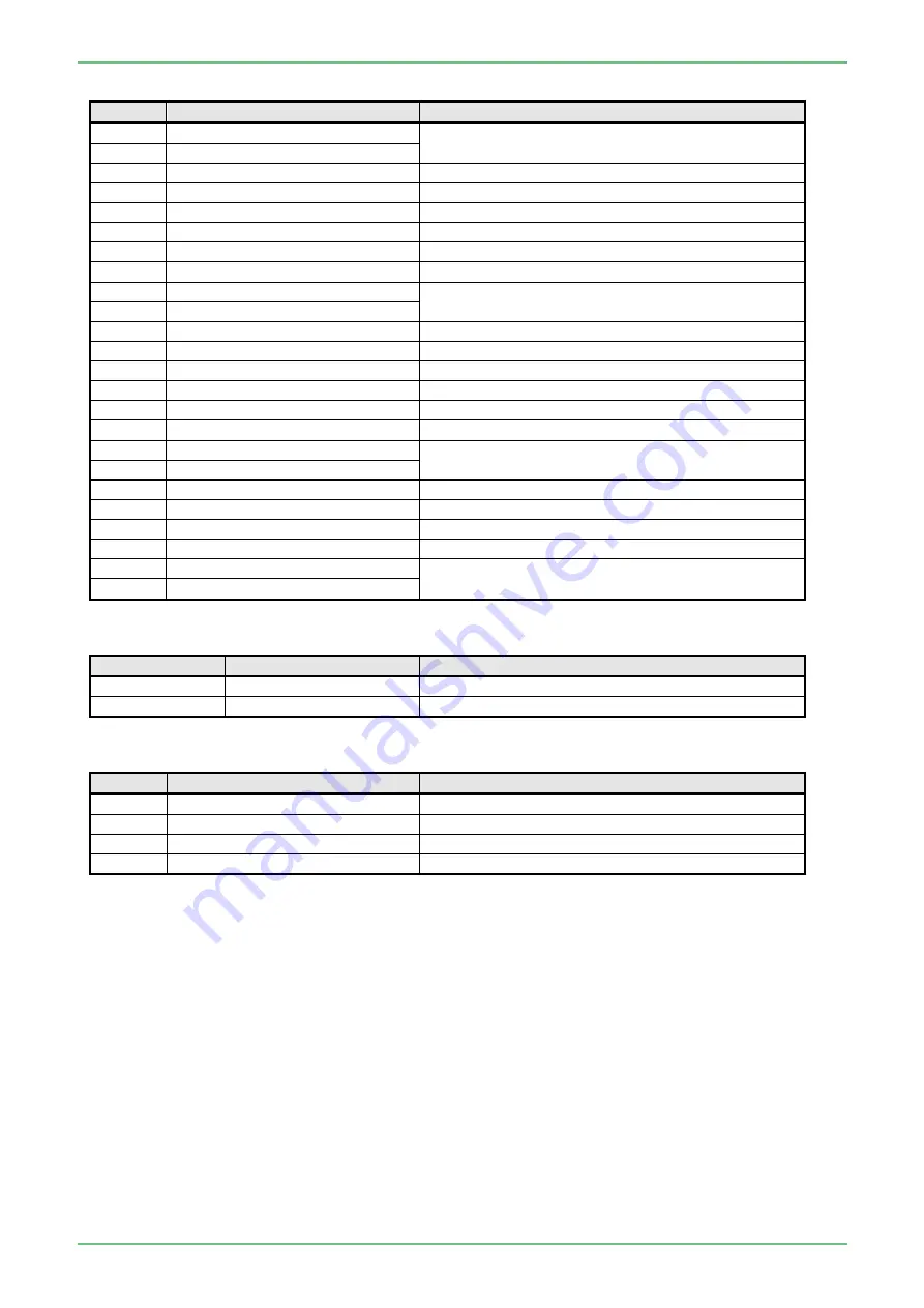
9.3.2 DVI (DVI-I
24 pins)
Pin No.
Name of signals
Remarks
1
T.M.D.S. Data 2-
R signal (8 bit) pair
,
without control signal
2
T.M.D.S. Data 2+
3
T.M.D.S. Data 2 Shield
R signal return GND
4
NC
5
NC
6
SCL
DDC Clock
7
SDA
DDC Data
8
NC
9
T.M.D.S. Data 1-
G signal (8 bit) pair
,
without control signal
10
T.M.D.S. Data 1+
11
T.M.D.S. Data 1 Shield
G signal return GND
12
NC
13
NC
14
+5V
POWER
15
GND
16
Hot Plag Detect
Hot plug detection
17
T.M.D.S.Data 0-
B signal (8 bit) pair +H SYNC + V SYNC
18
T.M.D.S.Data 0+
19
T.M.D.S.Data 0 Shield
B signal return GND
20
NC
21
NC
22
T.M.D.S.Clock Shield
Clock return GND
23
T.M.D.S.Clock+
Clock output pair
24
T.M.D.S.Clock-
9.3.3 Video
(BNC)
Pin No.
Name of signals
Remarks
Center contact
VBS
1Vp-p (signal 100% / 75Ω at the time of termination)
Outer case
AGND
GND
9.3.4 S-VIDEO(Y/C)
Mini DIN 4 pins
Pin No.
Name of signals
Remarks
1
GND
GND
2
GND
GND
3
Y
Y signal
4
C
C signal
Summary of Contents for EP-6000
Page 1: ...Processor EP 6000 FV693A Service Manual SR1807 N002 Ver 1 Oct 2018 ...
Page 5: ...SS1807 N002 General Table of Contents 1 1 General Table of Contents ...
Page 13: ...SS1807 N002 Caution in Safety 1 12 Caution in Safety ...
Page 25: ...SS1807 N002 Product Specifications 1 11 Product Specifications ...
Page 36: ...SS1807 N002 Instruction of System 1 106 Instruction of System ...
Page 133: ...SS1807 N002 Instruction of System 98 106 ELC PCB Patient PCB APC PCB APC PCB APC PCB DC Pump ...
Page 139: ...SS1807 N002 Instruction of System 104 106 9 4 Outline of PCB roles ...
Page 142: ...SS1807 N002 Failure Analysis 1 64 Failure Analysis ...
Page 206: ...SS1807 N002 Checkup Replacement and Adjustment 1 137 Checkup Replacement and Adjustment ...
Page 343: ...SS1807 N002 Service Parts List 1 19 Service Parts List ...
Page 352: ...SS1807 N002 Service Parts List 10 19 2 2 2 4 1 3 3 2 3 3 6 5 ...
Page 356: ...SS1807 N002 Service Parts List 14 19 1 3 3 4 1 2 1 3 X 4 1 3 3 4 3 3 ...
Page 358: ...SS1807 N002 Service Parts List 16 19 3 1 2 1 ...
Page 360: ...SS1807 N002 Service Parts List 18 19 Fig 09 5 4 2 3 1 ...
Page 362: ...SS1807 N002 Periodical Maintenance 1 15 Periodical Maintenance ...
Page 377: ...SS1807 N002 Installation 1 68 Installation ...
Page 445: ...SS1807 N002 ...


