


SS1807-N002
Failure Analysi
-
43/64
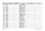
Display
error
code
Classification
level
Display message
(occurrence, response)
Display message
(guidance to
error)
Estimated cause
Trigger of message display
Service response
20049
Error
Unplug and plug back
endoscope, reset the
processor. If the problem
persists, contact your
local FUJIFILM dealer.
Cause: Light
source unit is in
abnormal state.
(LFCPU) Abnormality with FPGA
Error message: 0x2000
20050
Information
Initializing endoscope.
Please wait for a while.
(LFCPU) At the time of
reinitialization of scope
Error message: 0x4000
20051
Error
Check the cable
connection of WC-LINK
terminal, turn off and on
the processor.
Cause: The
WC-LINK cable is
connected
improperly.
(RCPU) Abnormal image
Error message: 0x8000
20052
Information
"Special Light Ob. mode"
is not available for this
endoscope.
20053
Error
Unplug and plug back
endoscope, reset the
processor. If the problem
persists, contact your
local FUJIFILM dealer.
Cause: The
patient circuit is in
abnormal state.
Patient PCB failure
At the time of AFE_FPGA
initialization,
CONF_DONE/INIT_DONE is not
changed to High in three
seconds.
20054
Error
Unplug and plug back
endoscope, reset the
processor. If the problem
persists, contact your
local FUJIFILM dealer.
Cause: The FPGA
of patient circuit is
in abnormal state.
Version upgrade failure
The version of AFE_FPGA is not
2.XX.
30035
Information
Preset setting screen startup
30036
Information
Preset setting screen end
30044
Information
Checking the connection
with the light source.
Please wait.
“Yes” was selected in the 916
dialog.
30076
Information
The attempted operation
cannot be performed in
the current state.
30077
Information
The "FICE" function isn't
available for this
endoscope.
(Only for gastrointestinal
endoscopes registered in
this system.)
An attempt to switch between
FICE ON and simple FICE was
made in a scope with destination
USA and other than for digestive
organs.
FICE ON
Summary of Contents for EP-6000
Page 1: ...Processor EP 6000 FV693A Service Manual SR1807 N002 Ver 1 Oct 2018 ...
Page 5: ...SS1807 N002 General Table of Contents 1 1 General Table of Contents ...
Page 13: ...SS1807 N002 Caution in Safety 1 12 Caution in Safety ...
Page 25: ...SS1807 N002 Product Specifications 1 11 Product Specifications ...
Page 36: ...SS1807 N002 Instruction of System 1 106 Instruction of System ...
Page 133: ...SS1807 N002 Instruction of System 98 106 ELC PCB Patient PCB APC PCB APC PCB APC PCB DC Pump ...
Page 139: ...SS1807 N002 Instruction of System 104 106 9 4 Outline of PCB roles ...
Page 142: ...SS1807 N002 Failure Analysis 1 64 Failure Analysis ...
Page 206: ...SS1807 N002 Checkup Replacement and Adjustment 1 137 Checkup Replacement and Adjustment ...
Page 343: ...SS1807 N002 Service Parts List 1 19 Service Parts List ...
Page 352: ...SS1807 N002 Service Parts List 10 19 2 2 2 4 1 3 3 2 3 3 6 5 ...
Page 356: ...SS1807 N002 Service Parts List 14 19 1 3 3 4 1 2 1 3 X 4 1 3 3 4 3 3 ...
Page 358: ...SS1807 N002 Service Parts List 16 19 3 1 2 1 ...
Page 360: ...SS1807 N002 Service Parts List 18 19 Fig 09 5 4 2 3 1 ...
Page 362: ...SS1807 N002 Periodical Maintenance 1 15 Periodical Maintenance ...
Page 377: ...SS1807 N002 Installation 1 68 Installation ...
Page 445: ...SS1807 N002 ...


