SS1807-N002
Checkup, Replacement and Adjustment
-
65/137
1.1.24 Main PCB
◆
Instruction
◆
・
As customer's config data is saved in the main PCB, save the config data in an external memory if
backup is possible to execute before the replacement of PCB, and restore the config data after the
replacement of PCB.
・
As the main PCB of service parts is in the condition of delivery inspection, therefore execute a
factory reset when installing in the processor.
In this case, as destination setting will be reset, execute destination setting after factory reset.
■ Storing procedures of Config Data
(1) Connect the USB memory on which the config data was stored to EP-6000.
◆
Note
◆
・
For the external memory, prepare and use EP-6000 dedicated one.
If you use an external memory that performed saving other than in EP-6000, the configuration
data may not be correctly saved.
(2) Connect keyboard and the monitor to EP-6000 and turn ON the power.
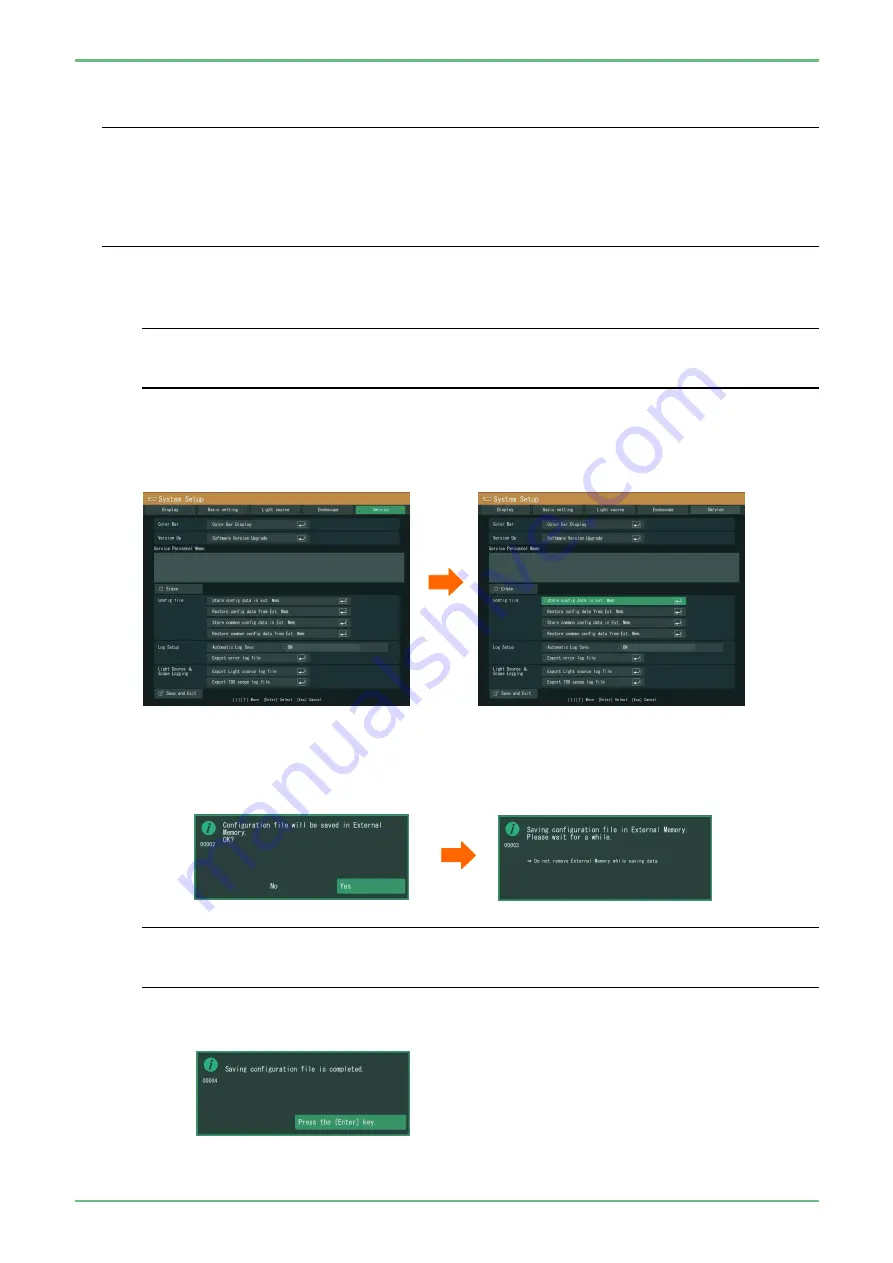
(3) Press the [Shift] + [Alt] + [System] keys of keyboard to display the system setup menu.
(4) Move the cursor to "Service".
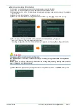
(5) Move the cursor to “Store config data in Ext. Mem” and press the [Enter] key.
(6) The message "Configuration file will be saved in External Memory." appears. Move the cursor to
"Yes" and press the [Enter] key.
The message "Saving configuration file in External Memory." appears, and saving the
configuration starts.
◆
Note
◆
・
Do not touch the processor until the message "Saving configuration file is completed"
appears.
If you turn off the power while saving config data, configuration file may not properly be saved.
(7) When the message "Saving configuration file is completed" appears, press the [Enter] key to
close the menu.
Summary of Contents for EP-6000
Page 1: ...Processor EP 6000 FV693A Service Manual SR1807 N002 Ver 1 Oct 2018 ...
Page 5: ...SS1807 N002 General Table of Contents 1 1 General Table of Contents ...
Page 13: ...SS1807 N002 Caution in Safety 1 12 Caution in Safety ...
Page 25: ...SS1807 N002 Product Specifications 1 11 Product Specifications ...
Page 36: ...SS1807 N002 Instruction of System 1 106 Instruction of System ...
Page 133: ...SS1807 N002 Instruction of System 98 106 ELC PCB Patient PCB APC PCB APC PCB APC PCB DC Pump ...
Page 139: ...SS1807 N002 Instruction of System 104 106 9 4 Outline of PCB roles ...
Page 142: ...SS1807 N002 Failure Analysis 1 64 Failure Analysis ...
Page 206: ...SS1807 N002 Checkup Replacement and Adjustment 1 137 Checkup Replacement and Adjustment ...
Page 343: ...SS1807 N002 Service Parts List 1 19 Service Parts List ...
Page 352: ...SS1807 N002 Service Parts List 10 19 2 2 2 4 1 3 3 2 3 3 6 5 ...
Page 356: ...SS1807 N002 Service Parts List 14 19 1 3 3 4 1 2 1 3 X 4 1 3 3 4 3 3 ...
Page 358: ...SS1807 N002 Service Parts List 16 19 3 1 2 1 ...
Page 360: ...SS1807 N002 Service Parts List 18 19 Fig 09 5 4 2 3 1 ...
Page 362: ...SS1807 N002 Periodical Maintenance 1 15 Periodical Maintenance ...
Page 377: ...SS1807 N002 Installation 1 68 Installation ...
Page 445: ...SS1807 N002 ...


