


SS1807-N002
Checkup, Replacement and Adjustment
-
66/137
■ Removal Procedures
◆
Instruction
◆
・
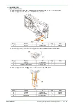
If [1] WC-LINK Cable has been connected, remove it before performing the procedures.
Key
Name
ID
Q’ty
Note
1
WC-LINK Cable
136Y121092*
1
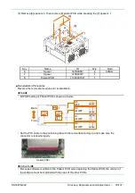
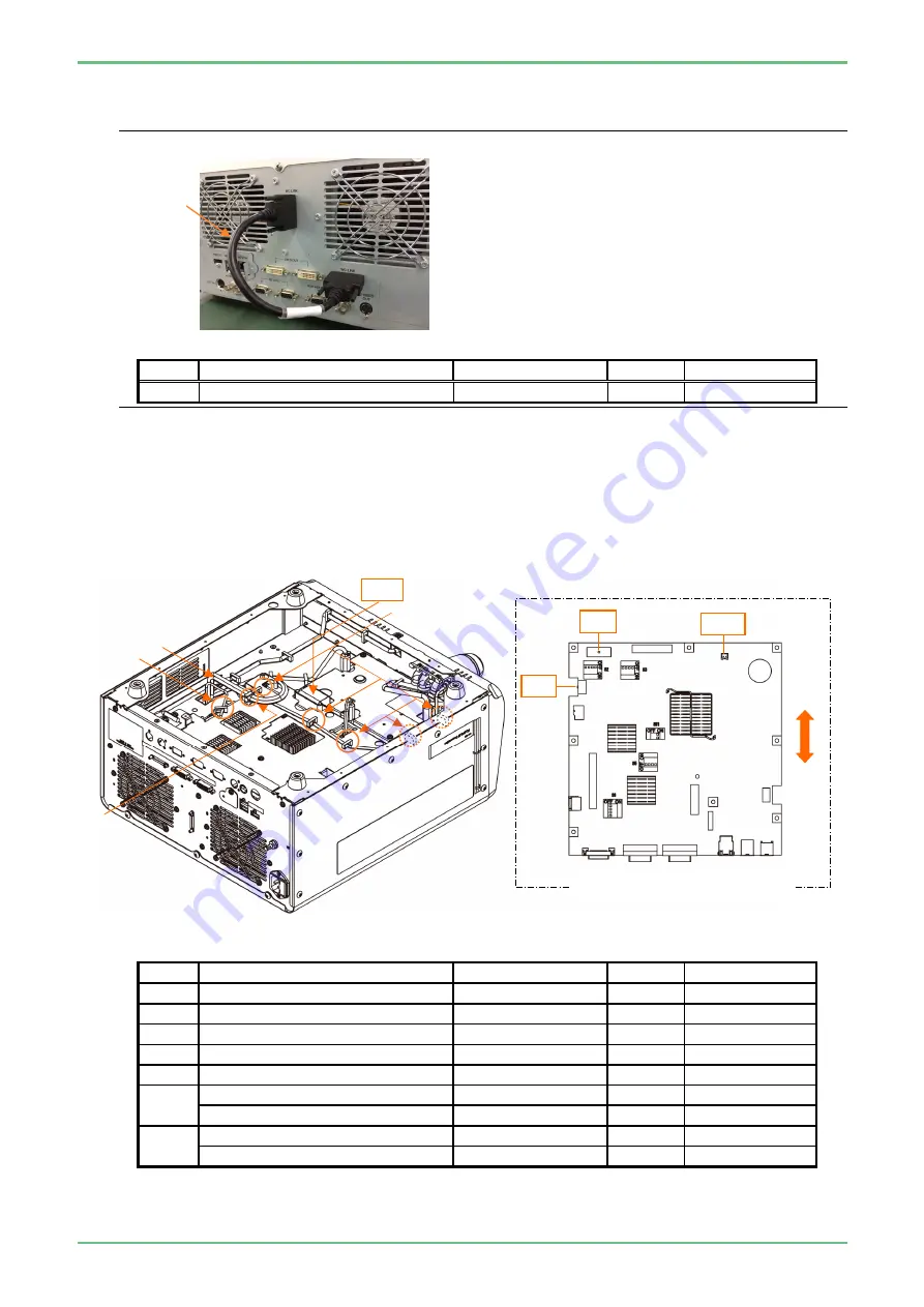
(1) Remove the Option PCB following the procedures (1) to (6) of “1.1. 23 IO/LORES PCB”.
(2) Open the [2] clamp x 1 and [3] clamp x1, harness ELC-Main/IOL free.
(3) Remove [4] harness ELC-Main/IOL from CN1 of main PCB.
(4) Open the [5] clamp x 5, then remove [6] harness Main-USB from CN6 of main PCB.
(5) Remove [7] harness Main-Patient from CN10 of main PCB.
(6) Remove [8] FFC Main-Patient from CN11 of main PCB.
Key
Name
ID
Q’ty
Note
2
Clamp
316S0259*
1
3
Clamp
316S1297*
1
4
Harness ELC-Main/IOL
136Y200452*
1
CN1
5
Clamp
316S0259*
5
6
Harness Main-USB
136Y121013*
1
CN6
7
Harness Main-Patient
136Y121192*
1
CN10
Ferrite Core
109S0029*
1
8
FFC Main-Patient
136Y200662*
1
CN11
Ferrite Core
138S0578*
1
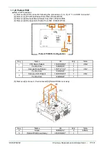
[1]
Main PCB Configuration
CN6
[6]
[4]
[2]
[5]
CN1
[4]
[7]
CN10
Back
Front
[3]
[8]
CN11
Summary of Contents for EP-6000
Page 1: ...Processor EP 6000 FV693A Service Manual SR1807 N002 Ver 1 Oct 2018 ...
Page 5: ...SS1807 N002 General Table of Contents 1 1 General Table of Contents ...
Page 13: ...SS1807 N002 Caution in Safety 1 12 Caution in Safety ...
Page 25: ...SS1807 N002 Product Specifications 1 11 Product Specifications ...
Page 36: ...SS1807 N002 Instruction of System 1 106 Instruction of System ...
Page 133: ...SS1807 N002 Instruction of System 98 106 ELC PCB Patient PCB APC PCB APC PCB APC PCB DC Pump ...
Page 139: ...SS1807 N002 Instruction of System 104 106 9 4 Outline of PCB roles ...
Page 142: ...SS1807 N002 Failure Analysis 1 64 Failure Analysis ...
Page 206: ...SS1807 N002 Checkup Replacement and Adjustment 1 137 Checkup Replacement and Adjustment ...
Page 343: ...SS1807 N002 Service Parts List 1 19 Service Parts List ...
Page 352: ...SS1807 N002 Service Parts List 10 19 2 2 2 4 1 3 3 2 3 3 6 5 ...
Page 356: ...SS1807 N002 Service Parts List 14 19 1 3 3 4 1 2 1 3 X 4 1 3 3 4 3 3 ...
Page 358: ...SS1807 N002 Service Parts List 16 19 3 1 2 1 ...
Page 360: ...SS1807 N002 Service Parts List 18 19 Fig 09 5 4 2 3 1 ...
Page 362: ...SS1807 N002 Periodical Maintenance 1 15 Periodical Maintenance ...
Page 377: ...SS1807 N002 Installation 1 68 Installation ...
Page 445: ...SS1807 N002 ...


