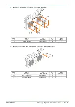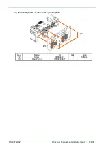
SS1807-N002
Checkup, Replacement and Adjustment
-
69/137
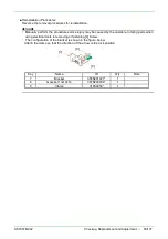
■ Reinstallation Procedures
Reverse the removal procedures for reinstallation.
◆
Note
◆
・
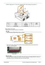
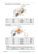
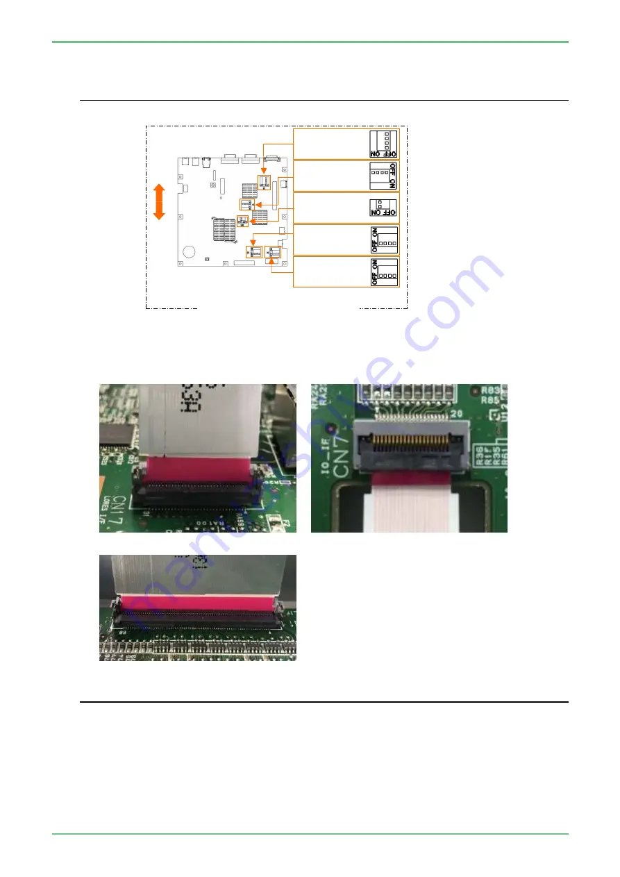
DIP SW setting of Main PCB is shown as below.
・
Set the FFC cable in the positioning tab with the red surface facing up and make sure the
connector is locked properly.
Locked(CN17)
Locked(CN7)
LOcked(CN11)
Main PCB DIP SW Setting
Front
Back
SW6
All OFF
SW5
All OFF
SW1
All ON
SW3
All OFF
SW2
All OFF
Summary of Contents for EP-6000
Page 1: ...Processor EP 6000 FV693A Service Manual SR1807 N002 Ver 1 Oct 2018 ...
Page 5: ...SS1807 N002 General Table of Contents 1 1 General Table of Contents ...
Page 13: ...SS1807 N002 Caution in Safety 1 12 Caution in Safety ...
Page 25: ...SS1807 N002 Product Specifications 1 11 Product Specifications ...
Page 36: ...SS1807 N002 Instruction of System 1 106 Instruction of System ...
Page 133: ...SS1807 N002 Instruction of System 98 106 ELC PCB Patient PCB APC PCB APC PCB APC PCB DC Pump ...
Page 139: ...SS1807 N002 Instruction of System 104 106 9 4 Outline of PCB roles ...
Page 142: ...SS1807 N002 Failure Analysis 1 64 Failure Analysis ...
Page 206: ...SS1807 N002 Checkup Replacement and Adjustment 1 137 Checkup Replacement and Adjustment ...
Page 343: ...SS1807 N002 Service Parts List 1 19 Service Parts List ...
Page 352: ...SS1807 N002 Service Parts List 10 19 2 2 2 4 1 3 3 2 3 3 6 5 ...
Page 356: ...SS1807 N002 Service Parts List 14 19 1 3 3 4 1 2 1 3 X 4 1 3 3 4 3 3 ...
Page 358: ...SS1807 N002 Service Parts List 16 19 3 1 2 1 ...
Page 360: ...SS1807 N002 Service Parts List 18 19 Fig 09 5 4 2 3 1 ...
Page 362: ...SS1807 N002 Periodical Maintenance 1 15 Periodical Maintenance ...
Page 377: ...SS1807 N002 Installation 1 68 Installation ...
Page 445: ...SS1807 N002 ...


