


SS1807-N002
Product Specifications
-
5/11
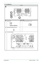
1.2.4 Accessories
1.3 Functions
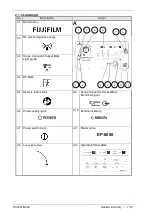
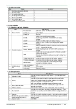
1.3.1 Button, switch, display
Item
Description
1
Power button
Push switch
Alternate action of ON and OFF
power on
green light
power off
light off
2
Operation panel
EXAM.
Switch on/off endoscope power
Switching of ACTIVE / STANDBY and status
display.
LIGHT
Switch on/off the light and status display.
PUMP
Switch H / M / L / OFF of air supply and status
display.
MULTI
Assign desired functions, such as L-LIMIT,FICE and
so on. and status display.
LIGHT MODE
Switch lighting mode to 1/2/3 / OFF and status
display.
IRIS
Switch Iris mode between AUTO, PEAK, and AVE
and status display.
Display the function setting screen by holding for 2
seconds
△
(Dimming level)
Change of dimming level and status display.
▽
(Dimming level)
Change of dimming level and status display.
NETWORK
none connected=off, connected=green light,
accessing=blinking orange
3
USB memory
slot
none connected
off
connected
green light
accessing
blinking orange
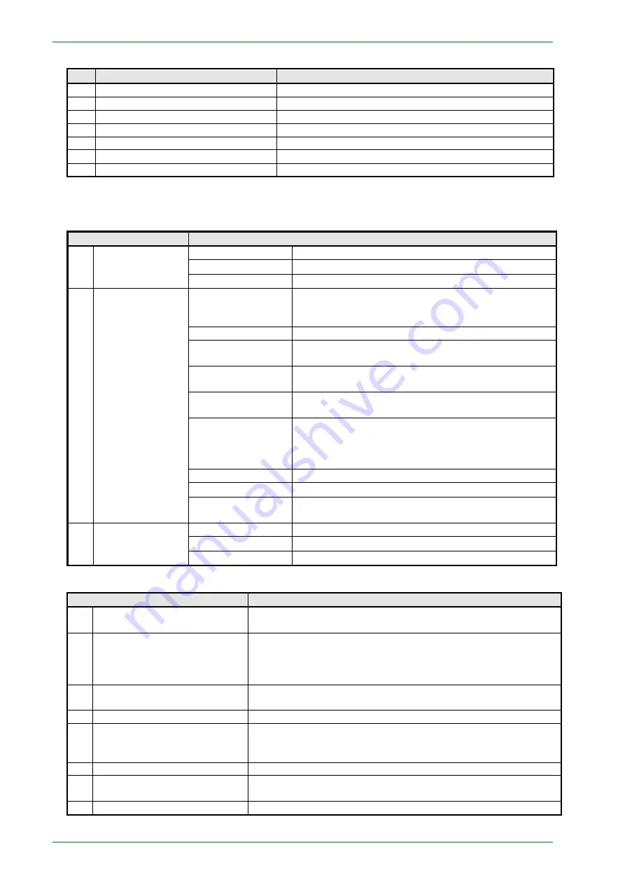
1.3.2 Peripherals
No.
Name
Quantity
1
Data key board DK-6000U
1
2
Power Cable
1
3
Operation Manual
1
4
Socket protection cap
1
5
Rover, Dust filter
1
6
WC-LINK cable
1
7
LAN connector guard
1
Item
Description
1
Data key board
Connect to Key board terminal (USB1.1) for operation and
settings
2
Printer
Connect to Remote terminal, peripheral device terminal
(RS-232C), Digital printer terminal (USB2.0) for image
capture and print-out of patient’s data
note: only capture is available with remote terminal
3
Still image recorder
Connect to remote terminal and store the captured still
images into media
4
Video recorder
Connect to remote terminal and control video recording
5
Foot switch
Connect to Foot switch terminal, and detect whether Foot
switch is on, and then control the functions assigned to Foot
switch
6
Reader
Connect to reader terminal (USB1.1) and read data of patient
7
Medical image work station,
DICOM gateway device
Connect to Network terminal for transmitting image and other
patient’s data
8
Serial control
UP-55MD
Summary of Contents for EP-6000
Page 1: ...Processor EP 6000 FV693A Service Manual SR1807 N002 Ver 1 Oct 2018 ...
Page 5: ...SS1807 N002 General Table of Contents 1 1 General Table of Contents ...
Page 13: ...SS1807 N002 Caution in Safety 1 12 Caution in Safety ...
Page 25: ...SS1807 N002 Product Specifications 1 11 Product Specifications ...
Page 36: ...SS1807 N002 Instruction of System 1 106 Instruction of System ...
Page 133: ...SS1807 N002 Instruction of System 98 106 ELC PCB Patient PCB APC PCB APC PCB APC PCB DC Pump ...
Page 139: ...SS1807 N002 Instruction of System 104 106 9 4 Outline of PCB roles ...
Page 142: ...SS1807 N002 Failure Analysis 1 64 Failure Analysis ...
Page 206: ...SS1807 N002 Checkup Replacement and Adjustment 1 137 Checkup Replacement and Adjustment ...
Page 343: ...SS1807 N002 Service Parts List 1 19 Service Parts List ...
Page 352: ...SS1807 N002 Service Parts List 10 19 2 2 2 4 1 3 3 2 3 3 6 5 ...
Page 356: ...SS1807 N002 Service Parts List 14 19 1 3 3 4 1 2 1 3 X 4 1 3 3 4 3 3 ...
Page 358: ...SS1807 N002 Service Parts List 16 19 3 1 2 1 ...
Page 360: ...SS1807 N002 Service Parts List 18 19 Fig 09 5 4 2 3 1 ...
Page 362: ...SS1807 N002 Periodical Maintenance 1 15 Periodical Maintenance ...
Page 377: ...SS1807 N002 Installation 1 68 Installation ...
Page 445: ...SS1807 N002 ...


