SS1807-N002
Product Specifications
-
7/11
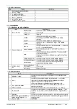
1.4 Auxiliary functions
1.5 Quality
No.
Item
Description
1
Data display
Display the selected patient data, and information about
the connected scope
2
switch Iris mode
Switch Iris mode (AUTO/PEAK/AVE 3 modes)
control the amount of light from light source, depending on
the levels of video signals
3
Electronic Zoom
zoom magnification
Enlarge the central part of image
× 1.00 ~ × 2.00 (0.05 step)
4
Peripheral device control
Control peripheral devices
5
Network
Transfer data via the network
6
Image enhancement function
FICE/BLI/BLI-bright/LCI
Process image created with wavelength components, and
emphasize the structure and area of the image that the
operator likes to focus on.
When combined with 500 system scope and 600 system
scope, FICE function is possible. 700 system scope,
EB-580S, FICE, BLI, BLI-bright and LCI functions are
possible.
7
Color adjustment
Adjust image color
8
Color Tone
Emphasize parts of image through color emphasis
9
Contour emphasis
Emphasize the contour of image
10
PinP(picture in picture)
When the observation screen displays a frozen image, still
or video image is displayed on the sub-screen.
11
Image stabilization
When freezing an image for printing or saving, shoot an
image with less blurring
12
Dual recording- FICE image
and regular image
With a single video recording operation, record both FICE
image and regular image simultaneously
13
Scope switch setting
Select and set functions to be assigned to the scope switch
14
Image mask change
A function to change the mask type of the image
15
LIGHT MODE
Switches the LIGHT MODE to “1”, “2”, “3” or “OFF”.
16
Automatic brightness
adjustment
Adjust the brightness of images to appropriate level by
processor control.
17
LIGHT switching
Switch the light source ON and OFF
18
Air supply pressure
switchover
Switches the air supply amount in the three levels of “H”,
“M” and “L”, or OFF
Item
Description
Period for Use
6 years
Period for Storage
6 years
Summary of Contents for EP-6000
Page 1: ...Processor EP 6000 FV693A Service Manual SR1807 N002 Ver 1 Oct 2018 ...
Page 5: ...SS1807 N002 General Table of Contents 1 1 General Table of Contents ...
Page 13: ...SS1807 N002 Caution in Safety 1 12 Caution in Safety ...
Page 25: ...SS1807 N002 Product Specifications 1 11 Product Specifications ...
Page 36: ...SS1807 N002 Instruction of System 1 106 Instruction of System ...
Page 133: ...SS1807 N002 Instruction of System 98 106 ELC PCB Patient PCB APC PCB APC PCB APC PCB DC Pump ...
Page 139: ...SS1807 N002 Instruction of System 104 106 9 4 Outline of PCB roles ...
Page 142: ...SS1807 N002 Failure Analysis 1 64 Failure Analysis ...
Page 206: ...SS1807 N002 Checkup Replacement and Adjustment 1 137 Checkup Replacement and Adjustment ...
Page 343: ...SS1807 N002 Service Parts List 1 19 Service Parts List ...
Page 352: ...SS1807 N002 Service Parts List 10 19 2 2 2 4 1 3 3 2 3 3 6 5 ...
Page 356: ...SS1807 N002 Service Parts List 14 19 1 3 3 4 1 2 1 3 X 4 1 3 3 4 3 3 ...
Page 358: ...SS1807 N002 Service Parts List 16 19 3 1 2 1 ...
Page 360: ...SS1807 N002 Service Parts List 18 19 Fig 09 5 4 2 3 1 ...
Page 362: ...SS1807 N002 Periodical Maintenance 1 15 Periodical Maintenance ...
Page 377: ...SS1807 N002 Installation 1 68 Installation ...
Page 445: ...SS1807 N002 ...

