


SS1807-N002
Checkup, Replacement and Adjustment
-
107/137
1.3.2 Checking the Power Supply
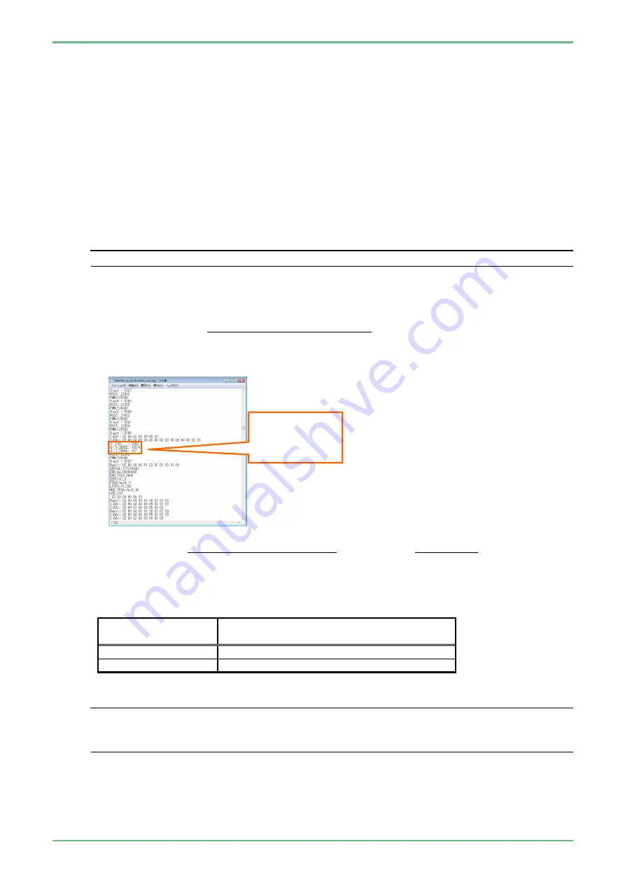
(1) Connect the external memory (with log data recorded) to a PC, and open
、
the file “××××××_vp_○○○○○○○○○_woc.lo” in the “¥ep6000¥log¥vp
_
○○○○○○○○○_●●●●●●●●¥scope” folder.
○
:
Serial number of the processor
●
:
Acquisition date of log data
×
:
Acquisition time of log data
(2) Search for the following 3 lines in the file.
Qi_FOD
(electrical power on scope side
mW)
Qi_V_SENSE
(voltage on light source side
mW)
Qi_I_SENSE
(electrical current on light source side mA)
◆
Note
◆
Log data is acquired per minute so the 3 lines above are also recorded per minute.
(3) Calculate the difference of power received.
Difference of
power received
=
(Qi_V_SENSE)×(Qi_I_SENSE)
- (Qi_FOD)
1000
Example
:
when using 760 series scope
Determination
value
=
(Qi_V_SENSE)×(Qi_I_SENSE)
- (Qi_FOD) =
18574 × 157
- 2060 = 856.118
1000
1000
(4) Measure it 3 times, check if the average value is in the standard range.
Scope type
Standard range for difference between
coil power supply and power received
760 series
800 to 1500mW
740 series
800 to 2000mW
◆
Note
◆
If the average value is not in the standard range, perform the following.
・
Replace the small cover unit.
・
Replace the WOC PCB.
Qi_FOD
Qi_V_SENSE
Qi_I_SENSE
Summary of Contents for EP-6000
Page 1: ...Processor EP 6000 FV693A Service Manual SR1807 N002 Ver 1 Oct 2018 ...
Page 5: ...SS1807 N002 General Table of Contents 1 1 General Table of Contents ...
Page 13: ...SS1807 N002 Caution in Safety 1 12 Caution in Safety ...
Page 25: ...SS1807 N002 Product Specifications 1 11 Product Specifications ...
Page 36: ...SS1807 N002 Instruction of System 1 106 Instruction of System ...
Page 133: ...SS1807 N002 Instruction of System 98 106 ELC PCB Patient PCB APC PCB APC PCB APC PCB DC Pump ...
Page 139: ...SS1807 N002 Instruction of System 104 106 9 4 Outline of PCB roles ...
Page 142: ...SS1807 N002 Failure Analysis 1 64 Failure Analysis ...
Page 206: ...SS1807 N002 Checkup Replacement and Adjustment 1 137 Checkup Replacement and Adjustment ...
Page 343: ...SS1807 N002 Service Parts List 1 19 Service Parts List ...
Page 352: ...SS1807 N002 Service Parts List 10 19 2 2 2 4 1 3 3 2 3 3 6 5 ...
Page 356: ...SS1807 N002 Service Parts List 14 19 1 3 3 4 1 2 1 3 X 4 1 3 3 4 3 3 ...
Page 358: ...SS1807 N002 Service Parts List 16 19 3 1 2 1 ...
Page 360: ...SS1807 N002 Service Parts List 18 19 Fig 09 5 4 2 3 1 ...
Page 362: ...SS1807 N002 Periodical Maintenance 1 15 Periodical Maintenance ...
Page 377: ...SS1807 N002 Installation 1 68 Installation ...
Page 445: ...SS1807 N002 ...


