SS1807-N002
Checkup, Replacement and Adjustment
-
112/137
No.
Inspection items
Inspection specification
How to inspect
Remarks
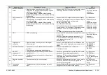
3
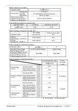
1) Earth leakage
current
The value should be below
the value shown in [Table 5].
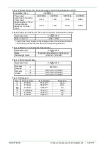
1) Set the test voltage to the power input
and frequency in [Table 4].
2) Disconnect all output cables.
3) Turn ON the power to the device to be
measured, stop the pump, and leave in
this state for more than 5 minutes.
4) Read the leakage current value in
each state.
*The measurement condition refers to
[Table 5].
JIG/Equipment
・
Leakage current
tester
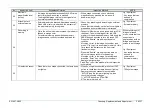
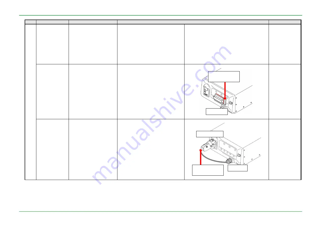
2) Enclosure
leakage current
The value should be below
the value shown in [Table 5].
1) Set the test voltage to the power input
and frequency in [Table 4].
2) Disconnect all output cables.
3) Turn ON the power to the device to be
measured, stop the pump, and leave in
this state for more than 5 minutes.
4) Apply the enclosure leakage current
test Jig “Y11N034” to the operation
panel, connect the probe of the leakage
current tester, and read the leakage
current value in each state.
*The measurement condition refers to
[Table 5].
JIG/Equipment
・
Leakage current
tester
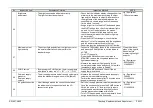
3) Patient leakage
current I
The value should be below
the value shown in [Table 5].
1) Set the test voltage to the power input
and frequency in [Table 4].
2) Disconnect all output cables.
3) Connect the “842Y130002*” jig and
“J57722” jig to the processor
4) Connect the probe on leakage current
tester to the “842Y130002*” jig and the
“J57722” jig.
5) Turn ON the power to the device to be
measured, stop the pump, and leave in
this state for more than 5 minutes.
6) Read the leakage current value in
each state.
*The measurement condition refers to
[Table 5]
JIG/Equipment
・
Leakage current
tester
・
842Y130002*
・
J57722
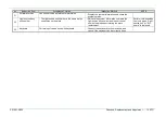
J57722
Probe on leakage
current tester
842Y130002*
Y11N0346
Probe on leakage
current tester
Summary of Contents for EP-6000
Page 1: ...Processor EP 6000 FV693A Service Manual SR1807 N002 Ver 1 Oct 2018 ...
Page 5: ...SS1807 N002 General Table of Contents 1 1 General Table of Contents ...
Page 13: ...SS1807 N002 Caution in Safety 1 12 Caution in Safety ...
Page 25: ...SS1807 N002 Product Specifications 1 11 Product Specifications ...
Page 36: ...SS1807 N002 Instruction of System 1 106 Instruction of System ...
Page 133: ...SS1807 N002 Instruction of System 98 106 ELC PCB Patient PCB APC PCB APC PCB APC PCB DC Pump ...
Page 139: ...SS1807 N002 Instruction of System 104 106 9 4 Outline of PCB roles ...
Page 142: ...SS1807 N002 Failure Analysis 1 64 Failure Analysis ...
Page 206: ...SS1807 N002 Checkup Replacement and Adjustment 1 137 Checkup Replacement and Adjustment ...
Page 343: ...SS1807 N002 Service Parts List 1 19 Service Parts List ...
Page 352: ...SS1807 N002 Service Parts List 10 19 2 2 2 4 1 3 3 2 3 3 6 5 ...
Page 356: ...SS1807 N002 Service Parts List 14 19 1 3 3 4 1 2 1 3 X 4 1 3 3 4 3 3 ...
Page 358: ...SS1807 N002 Service Parts List 16 19 3 1 2 1 ...
Page 360: ...SS1807 N002 Service Parts List 18 19 Fig 09 5 4 2 3 1 ...
Page 362: ...SS1807 N002 Periodical Maintenance 1 15 Periodical Maintenance ...
Page 377: ...SS1807 N002 Installation 1 68 Installation ...
Page 445: ...SS1807 N002 ...


