SS1807-N002
Checkup, Replacement and Adjustment
-
114/137
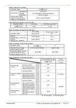
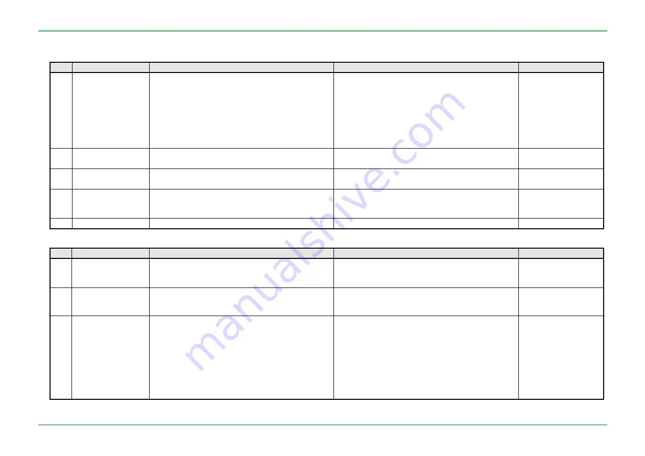
2.4 Operation check
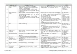
2.4.1 Appearance
No.
Inspection Item
Acceptance Criterion
Inspection Method
NOTE
1
All sides of the
equipment
・
There is no crack, deformation or irregularity that
negatively impacts the function/performance.
・
There is no rust or taint that negatively impact the
function/performance of electrical connector.
・
There is no breakage, deformation on WC-LINK
cable terminal.
・
Each screw on the rear panel must be fully
tightened.
・
Check the appearance of front, rear, left/right
sides and top of the main unit.
・
Check the appearance of the electrical connector.
・
Check the appearance of the WC-LINK cable
terminal.
・
Touch and check each screw on the rear panel by
hand.
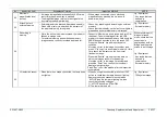
2
Specification plate
Caution label
・
The plate is adhered in the correct position.
・
The adhered label is correct.
・
Visually check the position of the plate and label,
and read the descriptions on them.
3
FOE
label
・
The label are adhered in the correct position.
・
The adhered label is correct.
・
Visually check the position of FOE label, and read
the description on it.
4
Silk printing
・
There is nothing lacking and skew on the printing.
・
Visually check the printing on the front and rear
panel.
・
Visually check the information mark.
5
Fuse
・
The T3.15A H250V fuse is mounted.
・
Remove the fuse to check the rated value.
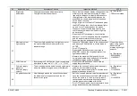
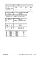
2.4.2 Function
No.
Inspection Item
Acceptance Criterion
Inspection Method
NOTE
1
Dustproof Filter
・
There is not problem with attaching the dustproof
filter.
・
The filter is not clogged with dust or the like.
・
Remove the dustproof filter to check it.
2
Attach / detach the
electrical connector
・
The electrical connector can be smoothly
attached and detached.
・
Detach and attach the electrical connector to
check it.
Jig / Equipment
・
500 system scope or
600 system scope
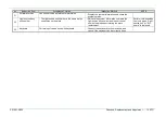
3
Scope connection /
disconnection
・
The scope can be connected smoothly to the lock
position of the scope connector socket.
・
The pull-out force of one-step connector is in
standard range.
・
Check that the LG connector can be pushed to
the lock position of the scope connector socket.
・
Check that the scope can be connected smoothly
and firmly.
* Check this item for 500 system scope or 600 / 700
system scope.
・
Use the measurement jig to measure the pull-out
force of one-step connector, and check if the
value is within the criterion in [Table7].
Jig / Equipment
・
500 system scope or
600 system scope
・
700 system scope
・
842Y130002*
・
Y20N100002
Summary of Contents for EP-6000
Page 1: ...Processor EP 6000 FV693A Service Manual SR1807 N002 Ver 1 Oct 2018 ...
Page 5: ...SS1807 N002 General Table of Contents 1 1 General Table of Contents ...
Page 13: ...SS1807 N002 Caution in Safety 1 12 Caution in Safety ...
Page 25: ...SS1807 N002 Product Specifications 1 11 Product Specifications ...
Page 36: ...SS1807 N002 Instruction of System 1 106 Instruction of System ...
Page 133: ...SS1807 N002 Instruction of System 98 106 ELC PCB Patient PCB APC PCB APC PCB APC PCB DC Pump ...
Page 139: ...SS1807 N002 Instruction of System 104 106 9 4 Outline of PCB roles ...
Page 142: ...SS1807 N002 Failure Analysis 1 64 Failure Analysis ...
Page 206: ...SS1807 N002 Checkup Replacement and Adjustment 1 137 Checkup Replacement and Adjustment ...
Page 343: ...SS1807 N002 Service Parts List 1 19 Service Parts List ...
Page 352: ...SS1807 N002 Service Parts List 10 19 2 2 2 4 1 3 3 2 3 3 6 5 ...
Page 356: ...SS1807 N002 Service Parts List 14 19 1 3 3 4 1 2 1 3 X 4 1 3 3 4 3 3 ...
Page 358: ...SS1807 N002 Service Parts List 16 19 3 1 2 1 ...
Page 360: ...SS1807 N002 Service Parts List 18 19 Fig 09 5 4 2 3 1 ...
Page 362: ...SS1807 N002 Periodical Maintenance 1 15 Periodical Maintenance ...
Page 377: ...SS1807 N002 Installation 1 68 Installation ...
Page 445: ...SS1807 N002 ...


