


SS1807-N002
Checkup, Replacement and Adjustment
-
115/137
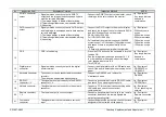
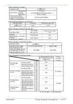
No.
Inspection Item
Acceptance Criterion
Inspection Method
NOTE
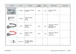
4
Power button
・
The power is surely turned ON and the indicator
lights in green when the power button is pressed.
・
The power and the indicator lamp is turned OFF
when the power button is switch off.
・
Connect to the power supplies listed in [Table4]
and press the power button to check if the
indicator lights up and the power is turned ON.
・
Switch off the power button and check if the
power and indicator lamp are turned OFF.
・
Check if the power button can be operated
smoothly.
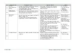
5
EXAM button
・
The EXAM button and the “STANDBY” lights in
orange when the power is turned ON without a
scope connected.
・
The buzzer sounds when the EXAM button is
pressed.
・
After connecting a scope and pressing the EXAM
button with the EXAM button and the “STANDBY”
are lighting in orange:
1) The EXAM button and the “ACTIVE” lights in
blue and the “STANDBY” light is turn off.
2) The image is displayed on the screen.
・
After holding down the EXAM button for 2
seconds when the image is being displayed, the
EXAM button and the “STANDBY” lights in
orange, and the image vanishes.
・
Press the EXAM button and then visually check
the monitor, color of EXAM button, light (color) of
the indicator and the image displayed on the
screen.
・
Press the EXAM button and check if the buzzer
sounds.
Jig / Equipment
・
Any scope that can
be used in
combination.
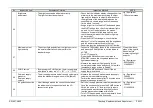
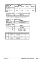
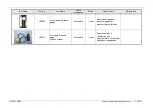
6
LIGHT button
・
Press the LIGHT button, then the lamp lights up,
the LIGHT button and the ON indicator lights in
blue.
・
Press the LIGHT button again, then the lamp is
turned off, the LIGHT button lights in orange and
the ON indicator is turned off.
・
The rotation speed of the fan is linked to the lamp
operation (lights up or not).
・
With a scope connected, press the LIGHT button
and check that the lamp lights up, the LIGHT
button and the ON indicator light in blue.
・
Press the LIGHT button again, check that the
LIGHT button lights in orange, the ON indicator is
turned off.
・
Check the rotation speed of the fan works as
following:
- When the lamp lights up: high-speed rotation
- When the lamp turned off: low-speed rotation
・
Check that the fans (x2) discharge the air.
Jig / Equipment
・
Any scope that can
be used in
combination.
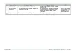
7
Brightness
Adjustment button
・
The light quantity increases with
▲
button, and
decreases with
▼
button.
・
With the light quantity changing, the display of the
indicator changes (increase or decrease).
・
With a scope connected and the lamp lighting up,
press the brightness adjustment button to check
the operation.
Jig / Equipment
・
Any scope that can
be used in
combination.
Summary of Contents for EP-6000
Page 1: ...Processor EP 6000 FV693A Service Manual SR1807 N002 Ver 1 Oct 2018 ...
Page 5: ...SS1807 N002 General Table of Contents 1 1 General Table of Contents ...
Page 13: ...SS1807 N002 Caution in Safety 1 12 Caution in Safety ...
Page 25: ...SS1807 N002 Product Specifications 1 11 Product Specifications ...
Page 36: ...SS1807 N002 Instruction of System 1 106 Instruction of System ...
Page 133: ...SS1807 N002 Instruction of System 98 106 ELC PCB Patient PCB APC PCB APC PCB APC PCB DC Pump ...
Page 139: ...SS1807 N002 Instruction of System 104 106 9 4 Outline of PCB roles ...
Page 142: ...SS1807 N002 Failure Analysis 1 64 Failure Analysis ...
Page 206: ...SS1807 N002 Checkup Replacement and Adjustment 1 137 Checkup Replacement and Adjustment ...
Page 343: ...SS1807 N002 Service Parts List 1 19 Service Parts List ...
Page 352: ...SS1807 N002 Service Parts List 10 19 2 2 2 4 1 3 3 2 3 3 6 5 ...
Page 356: ...SS1807 N002 Service Parts List 14 19 1 3 3 4 1 2 1 3 X 4 1 3 3 4 3 3 ...
Page 358: ...SS1807 N002 Service Parts List 16 19 3 1 2 1 ...
Page 360: ...SS1807 N002 Service Parts List 18 19 Fig 09 5 4 2 3 1 ...
Page 362: ...SS1807 N002 Periodical Maintenance 1 15 Periodical Maintenance ...
Page 377: ...SS1807 N002 Installation 1 68 Installation ...
Page 445: ...SS1807 N002 ...


