SS1807-N002
Checkup, Replacement and Adjustment
-
117/137
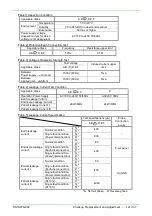
No.
Inspection Item
Acceptance Criterion
Inspection Method
NOTE
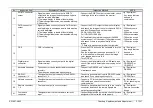
13
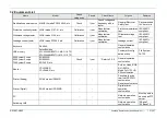
RGB TV connector
output
・
Signals must be correctly output to RGB TV
output and the image of endoscope and its data
must be correctly displayed.
1)
The image display is stable without blinking.
2) There is no significant noise, color deviation, blurring.
3) No hunting.
・
Connect the RGB TV output to the monitor, check
the image of the color chart on the monitor.
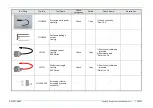
Jig / Equipment
・
Any scope that can
be used in
combination.
14
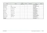
DVI-D connector
output
・
Signals must be correctly output to DVI-D output
and the image of endoscope and its data must be
correctly displayed.
1)
The image display is stable without blinking.
2) There is no significant noise, color deviation, blurring.
3) No hunting.
・
Connect the DVI-D output to the monitor, display
and check the image of the color chart with SXGA
and full HD respectively on the monitor.
SXGA
:
1280×1024 60p
Full HD
:
1920×1080 60p
・
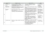
Pull and twist the electrical connector (500/600
system scope), LG connector (700 system scope)
and check if there is any abnormality on the
image.
* Check with each scope listed at the right side.
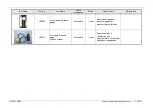
Jig / Equipment
・
530 honeycomb
scope
・
580 series scope
・
600 system scope
・
760 series scope
・
740 series scope
・
720 series scope
15
FICE
・
FICE is functioning.
・
Press the FICE button on the keyboard to turn the
function ON.
・
See the image from the scope and select 0, 1, 8
in order with numeric keypad, check the image
color change and return to 0.
・
Turn FICE off.
Jig / Equipment
・
Any scope that can
be used in
combination.
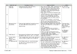
16
Digital printer
connector
・
Signals must be correctly output to the digital
printer terminal.
・
Connect the digital printer with a USB cable, and
check if the error is detected when running out of
paper.
Jig / Equipment
・
UP-D25MD or
CP-900D-F
17
Keyboard connector
・
The connector can be connected/disconnected
smoothly.
・
The menu can be operated with keyboard.
・
Connect the DK-6000, and retrieve the
maintenance menu.
Jig / Equipment
・
DK-6000
18
RS-232C
connector 1, 2
・
The signals are output correctly to the RS-232C
connector 1, 2.
・
Connect a peripheral device with RS-232C cable,
and check if you can properly control it.
Jig / Equipment
・
UP-55MD etc.
19
Network connector
・
The signals are output correctly to the network
connector.
・
Connect a PC for communication checking with a
LAN cable, and check the contents of
communication.
Jig / Equipment
・
PC for checking the
network
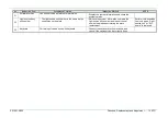
20
Remote connector
1, 2
・
The remote output is correctly output.
・
Connect a peripheral device or a jig to the remote
connector, and check the remote signals are
output by operating them.
Jig / Equipment
・
Remote connection
device
21
Foot switch
connector
・
The signals from the foot switch are correctly
input.
・
Connect and press the foot switch, check if functions
assigned to the foot switch works properly.
Jig / Equipment
・
FS-1
Summary of Contents for EP-6000
Page 1: ...Processor EP 6000 FV693A Service Manual SR1807 N002 Ver 1 Oct 2018 ...
Page 5: ...SS1807 N002 General Table of Contents 1 1 General Table of Contents ...
Page 13: ...SS1807 N002 Caution in Safety 1 12 Caution in Safety ...
Page 25: ...SS1807 N002 Product Specifications 1 11 Product Specifications ...
Page 36: ...SS1807 N002 Instruction of System 1 106 Instruction of System ...
Page 133: ...SS1807 N002 Instruction of System 98 106 ELC PCB Patient PCB APC PCB APC PCB APC PCB DC Pump ...
Page 139: ...SS1807 N002 Instruction of System 104 106 9 4 Outline of PCB roles ...
Page 142: ...SS1807 N002 Failure Analysis 1 64 Failure Analysis ...
Page 206: ...SS1807 N002 Checkup Replacement and Adjustment 1 137 Checkup Replacement and Adjustment ...
Page 343: ...SS1807 N002 Service Parts List 1 19 Service Parts List ...
Page 352: ...SS1807 N002 Service Parts List 10 19 2 2 2 4 1 3 3 2 3 3 6 5 ...
Page 356: ...SS1807 N002 Service Parts List 14 19 1 3 3 4 1 2 1 3 X 4 1 3 3 4 3 3 ...
Page 358: ...SS1807 N002 Service Parts List 16 19 3 1 2 1 ...
Page 360: ...SS1807 N002 Service Parts List 18 19 Fig 09 5 4 2 3 1 ...
Page 362: ...SS1807 N002 Periodical Maintenance 1 15 Periodical Maintenance ...
Page 377: ...SS1807 N002 Installation 1 68 Installation ...
Page 445: ...SS1807 N002 ...


