SS1807-N002
Checkup, Replacement and Adjustment
-
135/137
◆
Note
◆
・
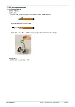
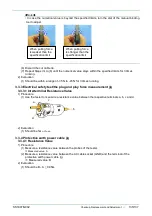
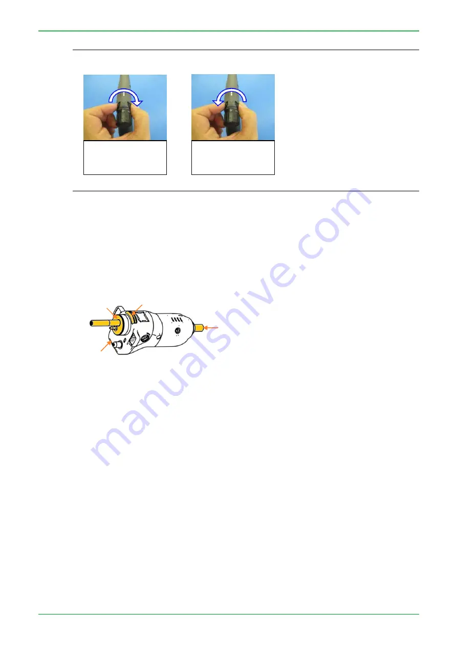
In case the numerical value is beyond the specified limits, turn the dial of the manual binding
tool to adjust.
(6) Discard the cut cable tie.
(7) Repeat Steps (3) to (6) until the numerical value stays within the specified limits for 3 times
running.
2) Evaluation
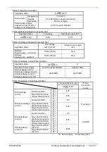
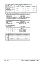
(1) Should be within a range of -35 N to -45 N for 3 times running.
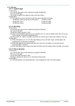
3.3.3 Electrical safety test/the plug and play force measurement jig
3.3.3.1
Interterminal Resistance Value
1) Procedure
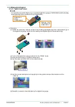
(1) Use the tester to measure a resistance value between the respective terminals a, b, c and d.
2) Evaluation
(1) Should be 1
Ω or less.
3.3.4 Protective earth power cable jig
3.3.4.1 Resistance Value
1) Procedure
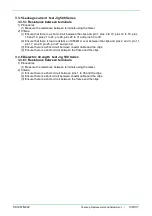
(1) Measure a resistance value between the probes of the tester.
⇒
Measured value: A
(2) Measure a resistance value between the AC cable socket (GND) and the terminal of the
protective earth power cable jig.
⇒
Measured value: B
2) Evaluation
(1) Should be B – A
≤
0.05
Ω
.
a
b
c
d
When pulling force
is weaker than the
specification limit
When pulling force
is stronger than the
specification limit
Summary of Contents for EP-6000
Page 1: ...Processor EP 6000 FV693A Service Manual SR1807 N002 Ver 1 Oct 2018 ...
Page 5: ...SS1807 N002 General Table of Contents 1 1 General Table of Contents ...
Page 13: ...SS1807 N002 Caution in Safety 1 12 Caution in Safety ...
Page 25: ...SS1807 N002 Product Specifications 1 11 Product Specifications ...
Page 36: ...SS1807 N002 Instruction of System 1 106 Instruction of System ...
Page 133: ...SS1807 N002 Instruction of System 98 106 ELC PCB Patient PCB APC PCB APC PCB APC PCB DC Pump ...
Page 139: ...SS1807 N002 Instruction of System 104 106 9 4 Outline of PCB roles ...
Page 142: ...SS1807 N002 Failure Analysis 1 64 Failure Analysis ...
Page 206: ...SS1807 N002 Checkup Replacement and Adjustment 1 137 Checkup Replacement and Adjustment ...
Page 343: ...SS1807 N002 Service Parts List 1 19 Service Parts List ...
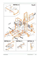
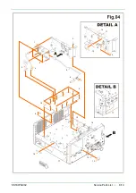
Page 352: ...SS1807 N002 Service Parts List 10 19 2 2 2 4 1 3 3 2 3 3 6 5 ...
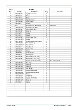
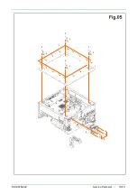
Page 356: ...SS1807 N002 Service Parts List 14 19 1 3 3 4 1 2 1 3 X 4 1 3 3 4 3 3 ...
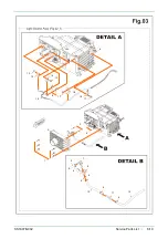
Page 358: ...SS1807 N002 Service Parts List 16 19 3 1 2 1 ...
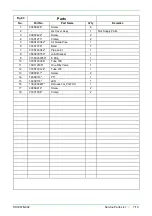
Page 360: ...SS1807 N002 Service Parts List 18 19 Fig 09 5 4 2 3 1 ...
Page 362: ...SS1807 N002 Periodical Maintenance 1 15 Periodical Maintenance ...
Page 377: ...SS1807 N002 Installation 1 68 Installation ...
Page 445: ...SS1807 N002 ...

