SS1807-N002
Periodical Maintenance
-
9/15
No.
Inspection items
Inspection specification
How to inspect
Remarks
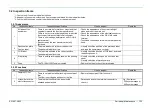
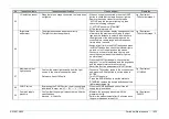
7
Brightness
Adjustment button
・
The light quantity increases with
▲
button, and
decreases with
▼
button.
・
With the light quantity changing, the display of the
indicator changes (increase or decrease).
・
With a scope connected and the lamp lighting up,
press the brightness adjustment button to check
the operation.
Jig / Equipment
・
Any scope that can
be used in
combination. *3
8
IRIS button
・
The LED lamp of its characters lights up.
・
The IRIS mode can be switched by pressing the
IRIS button. AUTO/PEAK/AVE
・
As the IRIS button is pressed, the display of IRIS
mode on the monitor and on the front panel
change.
・
Turn ON the power and check the LED lights up
on the front panel.
・
Take a image of a high-reflection object by a
scope and press the IRIS button, check that the
brightness of the image decreases (become
darker) when switching to PEAK mode.
Jig / Equipment
・
Any scope that can
be used in
combination. *3
9
MULTI button
・
The indicator lights up.
・
The functions set to the MULT button operate.
・
Turn ON the power, check the function set in the
Multi Button in the system setup menu.
・
Press the MULTI button, check the indicator lights
up and the function which has been set operates.
・
Press the MULTI button again, and check that the
indicator returns.
Jig / Equipment
・
Any scope that can
be used in
combination. *3
10
LIGHT MODE
button
・
The light mode can be switched by operating the
LIGHT MODE button.
・
Press the LIGHT MODE button one time, check
that the [1] lights up and the display is switched to
BLI mode.
・
Press the LIGHT MODE button one more time,
check that the [2] lights up and the display is
switched to BLI-bright mode.
・
Press the LIGHT MODE button one more time,
check that the [3] lights up and the display is
switched to LCI mode.
・
Press the LIGHT MODE button one more time,
check that the light of [1][2][3] is turned off and the
display returns to normal observation mode.
Jig / Equipment
・
700 system scope *3
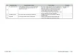
11
S video connector
output
・
Signals must be correctly output to S video output
and the image of endoscope and its data must be
correctly displayed.
1) The image display is stable without blinking.
2) There is no significant noise, color deviation, blurring.
3) No hunting.
・
Connect the S video output to the monitor, check
the image of the color chart on the monitor.
*1
Jig / Equipment
・
Any scope that can
be used in
combination. *3
Summary of Contents for EP-6000
Page 1: ...Processor EP 6000 FV693A Service Manual SR1807 N002 Ver 1 Oct 2018 ...
Page 5: ...SS1807 N002 General Table of Contents 1 1 General Table of Contents ...
Page 13: ...SS1807 N002 Caution in Safety 1 12 Caution in Safety ...
Page 25: ...SS1807 N002 Product Specifications 1 11 Product Specifications ...
Page 36: ...SS1807 N002 Instruction of System 1 106 Instruction of System ...
Page 133: ...SS1807 N002 Instruction of System 98 106 ELC PCB Patient PCB APC PCB APC PCB APC PCB DC Pump ...
Page 139: ...SS1807 N002 Instruction of System 104 106 9 4 Outline of PCB roles ...
Page 142: ...SS1807 N002 Failure Analysis 1 64 Failure Analysis ...
Page 206: ...SS1807 N002 Checkup Replacement and Adjustment 1 137 Checkup Replacement and Adjustment ...
Page 343: ...SS1807 N002 Service Parts List 1 19 Service Parts List ...
Page 352: ...SS1807 N002 Service Parts List 10 19 2 2 2 4 1 3 3 2 3 3 6 5 ...
Page 356: ...SS1807 N002 Service Parts List 14 19 1 3 3 4 1 2 1 3 X 4 1 3 3 4 3 3 ...
Page 358: ...SS1807 N002 Service Parts List 16 19 3 1 2 1 ...
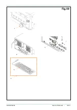
Page 360: ...SS1807 N002 Service Parts List 18 19 Fig 09 5 4 2 3 1 ...
Page 362: ...SS1807 N002 Periodical Maintenance 1 15 Periodical Maintenance ...
Page 377: ...SS1807 N002 Installation 1 68 Installation ...
Page 445: ...SS1807 N002 ...

