SS1807-N002
Periodical Maintenance
-
11/15
No.
Inspection items
Inspection specification
How to inspect
Remarks
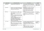
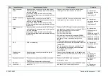
19
Network connector
・
The signals are output correctly to the network
connector.
・
Connect a PC for communication checking with a
LAN cable, and check the contents of
communication.
*1
Jig / Equipment
・
PC for checking the
network
20
Remote connector
1, 2
・
The remote output is correctly output.
・
Connect a peripheral device or a jig to the remote
connector, and check the remote signals are
output by operating them.
*1,*2
Jig / Equipment
・
Remote connection
device
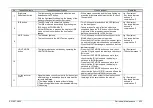
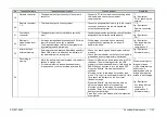
21
Foot switch
connector
・
The signals from the foot switch are correctly
input.
・
Connect and press the foot switch, check if functions
assigned to the foot switch works properly.
*1
Jig / Equipment
・
FS-1
22
Electronic
magnification level
(cursor)
・
An image is magnified electronically by 0.05 times
every time the up-arrow key is pressed.
・
The magnified image returns to the original size
by pressing the down-arrow key.
・
With a scope connected, check electronic
magnification by pressing the up-arrow &
down-arrow keys.
Jig / Equipment
・
Any scope that can
be used in
combination. *3
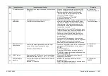
23
Attach / detach
external memory
・
External memory be attached & detached smoothly.
・
When USB memory is attached, the indicator of
the external memory turns green.
・
Check it by attaching and detaching an external
memory.
・
Check that the indicator on the front cover lights in
green when an external memory is attached.
Jig / Equipment
・
External memory
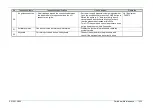
24
Recording to
memory
・
While the writing is being processed, the indicator
flashes in orange color.
・
For external memory and embedded memory,
Images can be correctly recorded and read out.
・
Connect USB memory and a scope, and turn ON
the power. Take in the images from the USB
memory to the embedded memory. Hold down the
EXAM button 2 seconds to turn the scope OFF.
Press the “Search” key and input a search
condition.
Move the cursor to the image list number, and
press “C” to copy it to an external memory. At this
time, check the indicator on the front cover
flashes in orange.
・
Press the “Search” key and input the date on
which the images taken in for searching.
Move the cursor to the image list number and
press the “Enter” key, check if the thumbnail
displays the right image.
Press “Esc” to exit the window after the inspection
is completed.
*1
When recording still
images in freeze
mode, check that the
sub screen is
displayed as a
video
image and the main
screen is a still image.
Jig / Equipment
・
Any scope that can
be used in
combination. *3
・
External memory
Summary of Contents for EP-6000
Page 1: ...Processor EP 6000 FV693A Service Manual SR1807 N002 Ver 1 Oct 2018 ...
Page 5: ...SS1807 N002 General Table of Contents 1 1 General Table of Contents ...
Page 13: ...SS1807 N002 Caution in Safety 1 12 Caution in Safety ...
Page 25: ...SS1807 N002 Product Specifications 1 11 Product Specifications ...
Page 36: ...SS1807 N002 Instruction of System 1 106 Instruction of System ...
Page 133: ...SS1807 N002 Instruction of System 98 106 ELC PCB Patient PCB APC PCB APC PCB APC PCB DC Pump ...
Page 139: ...SS1807 N002 Instruction of System 104 106 9 4 Outline of PCB roles ...
Page 142: ...SS1807 N002 Failure Analysis 1 64 Failure Analysis ...
Page 206: ...SS1807 N002 Checkup Replacement and Adjustment 1 137 Checkup Replacement and Adjustment ...
Page 343: ...SS1807 N002 Service Parts List 1 19 Service Parts List ...
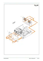
Page 352: ...SS1807 N002 Service Parts List 10 19 2 2 2 4 1 3 3 2 3 3 6 5 ...
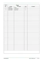
Page 356: ...SS1807 N002 Service Parts List 14 19 1 3 3 4 1 2 1 3 X 4 1 3 3 4 3 3 ...
Page 358: ...SS1807 N002 Service Parts List 16 19 3 1 2 1 ...
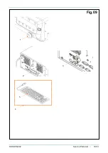
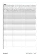
Page 360: ...SS1807 N002 Service Parts List 18 19 Fig 09 5 4 2 3 1 ...
Page 362: ...SS1807 N002 Periodical Maintenance 1 15 Periodical Maintenance ...
Page 377: ...SS1807 N002 Installation 1 68 Installation ...
Page 445: ...SS1807 N002 ...

