SS1807-N002
Periodical Maintenance
-
12/15
No.
Inspection items
Inspection specification
How to inspect
Remarks
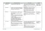
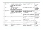
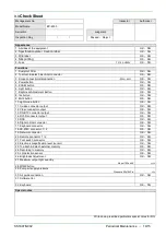
25
LG
detection sensor
・
When there is no scope connected, the lamp does
not light up.
・
When no scope is connected, press the LIGHT
button to check that the lamp does not light up.
・
Remove the scope connector socket when
“ACTIVE” and the lamp are lighting-up, then
check the following changes.
1) “ACTIVE” becomes “STANDBY”.
2) The lamp is turned off.
Jig / Equipment
・
700 system scope 3
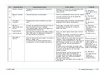
26
Brightness
adjustment
・
The brightness can be adjusted correctly.
・
The light limit functions properly.
・
Check that the indicator display changes from the
minimum to the maximum according to object
type and the distance to object. Also make sure
the brightness of the displayed image can be
controlled in a certain range and the response
time is within 1 second.
・
Assign a light limit to the MULTI button and press
the MULTI button, then check the indicator lights
up and “L-Limit” is displayed on the screen.
・
Connect a scope to let the lamp light up, and
check the scale marks of the indicator light up
no more than 7.
・
Press the MULTI button again, check that the
display of “L-Limit” disappears, and the brightness
and the indicator status revert to the first.
・
Revert the function assignment of MULTI button.
Jig / Equipment
・
700 system scope *3
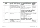
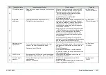
27
Maximum output
light quantity
・
Confirm the output light quantity from the light
source in the normal observation mode
Reference
:
About 192unit4
・
Connect a 700 system scope to the scope socket
and press the EXAM button to set the status to
ACTIVE.
・
Turn OFF the pump.
・
Press the EXAM button to set the status to
STANDBY, remove the scope and connect the
light measurement jig.
Jig / Equipment
・
Y11N0362
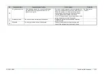
28
PUMP button
・
By pressing the PUMP button, the air supply lamp
is switched in order as: “H” → “M” → “L” → OFF
・
Press the PUMP button and check if the air
supply lamp is switched.
29
Pump air supply
pressure
・
Confirm that the pump air pressure are within the
specifications.
Standard
:
H
:
50±10kPa
・
Measure the air supply pressure with the
measurement jig.
* Perform the measurement after 10 minutes since
the power has been turned ON.
Jig / Equipment
・
JA5015
Summary of Contents for EP-6000
Page 1: ...Processor EP 6000 FV693A Service Manual SR1807 N002 Ver 1 Oct 2018 ...
Page 5: ...SS1807 N002 General Table of Contents 1 1 General Table of Contents ...
Page 13: ...SS1807 N002 Caution in Safety 1 12 Caution in Safety ...
Page 25: ...SS1807 N002 Product Specifications 1 11 Product Specifications ...
Page 36: ...SS1807 N002 Instruction of System 1 106 Instruction of System ...
Page 133: ...SS1807 N002 Instruction of System 98 106 ELC PCB Patient PCB APC PCB APC PCB APC PCB DC Pump ...
Page 139: ...SS1807 N002 Instruction of System 104 106 9 4 Outline of PCB roles ...
Page 142: ...SS1807 N002 Failure Analysis 1 64 Failure Analysis ...
Page 206: ...SS1807 N002 Checkup Replacement and Adjustment 1 137 Checkup Replacement and Adjustment ...
Page 343: ...SS1807 N002 Service Parts List 1 19 Service Parts List ...
Page 352: ...SS1807 N002 Service Parts List 10 19 2 2 2 4 1 3 3 2 3 3 6 5 ...
Page 356: ...SS1807 N002 Service Parts List 14 19 1 3 3 4 1 2 1 3 X 4 1 3 3 4 3 3 ...
Page 358: ...SS1807 N002 Service Parts List 16 19 3 1 2 1 ...
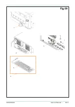
Page 360: ...SS1807 N002 Service Parts List 18 19 Fig 09 5 4 2 3 1 ...
Page 362: ...SS1807 N002 Periodical Maintenance 1 15 Periodical Maintenance ...
Page 377: ...SS1807 N002 Installation 1 68 Installation ...
Page 445: ...SS1807 N002 ...

