
SS1807-N002
Installation
-
2/68
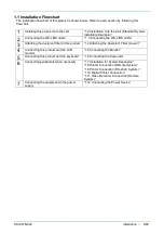
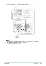
1. System Installation
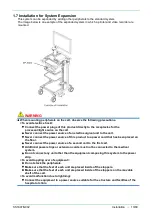
WARNING
・
If any peripherals not described in EP-6000 Operation Manual “2.2 Equipment Using in
Combination” are used, this
product may not function properly, and electric shock,
equipment damage, or injury to
patients or physicians may occur.
・
If the power cords of the peripherals are connected without using the insulation
transformer
on the cart, the enclosure leakage current may increase, posing a risk of injury
or electric
shock to the patient and/or the physician when he/she comes into contact with
those
devices.
・
When using a network, insert an EN 60601-1-compliant separator between the LAN cable,
which connects the devices, and the network system. If such a separator is not used,
the
enclosure leakage current may increase due to the current being leaked from the
connected
network system or due to the electric potential difference between grounds.
This may pose a risk of injury or electric shock to the patient and/or the physician when
he/she comes into contact with the devices.
・
This product conforms to the EMC standard (EN 60601-1-2: 2015). However, the radio
waves
radiated form this product may cause medical devices such as a pacemaker to
malfunction.
When this product is used for a patient with an active implantable medical
device, consult a
cardiovascular specialist and the manufacturer of the active implantable
medical device.
・
Use the rated voltage only. Not doing so may cause a fire or electric shock.
・
Connect the power plug directly to the protective earth receptacle. Use peripherals that are
compliant with the medical safety standards. Not doing so may cause an electric shock.
・
Do not use the equipment in atmosphere of flammable gas and oxygen-rich environment.
Doing so may cause explosion or fire.
・
Do not simultaneously touch the patient and any of the system devices in the patient
environment. Doing so may cause electric shock.
・
If the power cords of the peripherals are connected without using the insulation transformer
on the cart, the enclosure leakage current may increase, posing a risk of injury or electric
shock to the patient and/or the physician when he/she comes into contact with those
devices.
CAUTION
・
Configure the ME system in accordance with the maximum allowable current of the power
strip to be used.
・
If a peripheral is used, connect it to a receptacle via an insulating transformer.
Connect peripherals in accordance with the specification of the insulating transformer.
・
Use the multi-tap installed in the cart only for the equipment used for this system. If it is
used for other equipment, the current capacity may increase and the equipment may not
operate properly.
・
There are ventilation holes on the left and rear side of this product. Take care not to cover
them with other objects.
・
Use the rated voltage only. Not doing so may cause a fire, electric shock or malfunction.
・
Install equipment in a location in which the power cord or connected endoscope will not
become entangled. Equipment may fall over or down, the screen may go black, or the patient
or operator may be injured.
Summary of Contents for EP-6000
Page 1: ...Processor EP 6000 FV693A Service Manual SR1807 N002 Ver 1 Oct 2018 ...
Page 5: ...SS1807 N002 General Table of Contents 1 1 General Table of Contents ...
Page 13: ...SS1807 N002 Caution in Safety 1 12 Caution in Safety ...
Page 25: ...SS1807 N002 Product Specifications 1 11 Product Specifications ...
Page 36: ...SS1807 N002 Instruction of System 1 106 Instruction of System ...
Page 133: ...SS1807 N002 Instruction of System 98 106 ELC PCB Patient PCB APC PCB APC PCB APC PCB DC Pump ...
Page 139: ...SS1807 N002 Instruction of System 104 106 9 4 Outline of PCB roles ...
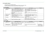
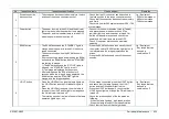
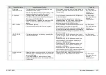
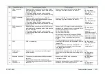
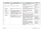
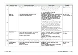
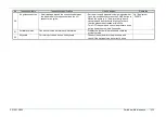
Page 142: ...SS1807 N002 Failure Analysis 1 64 Failure Analysis ...
Page 206: ...SS1807 N002 Checkup Replacement and Adjustment 1 137 Checkup Replacement and Adjustment ...
Page 343: ...SS1807 N002 Service Parts List 1 19 Service Parts List ...
Page 352: ...SS1807 N002 Service Parts List 10 19 2 2 2 4 1 3 3 2 3 3 6 5 ...
Page 356: ...SS1807 N002 Service Parts List 14 19 1 3 3 4 1 2 1 3 X 4 1 3 3 4 3 3 ...
Page 358: ...SS1807 N002 Service Parts List 16 19 3 1 2 1 ...
Page 360: ...SS1807 N002 Service Parts List 18 19 Fig 09 5 4 2 3 1 ...
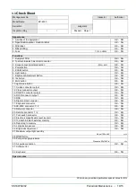
Page 362: ...SS1807 N002 Periodical Maintenance 1 15 Periodical Maintenance ...
Page 377: ...SS1807 N002 Installation 1 68 Installation ...
Page 445: ...SS1807 N002 ...


