


SS1807-N002
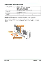
Installation
-
38/68
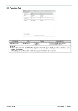
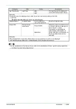
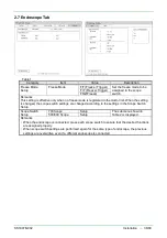
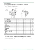
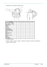
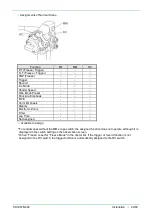
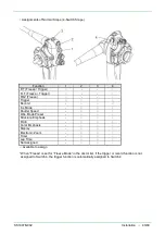
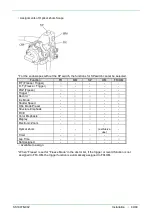
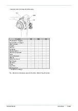
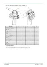
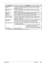
<Functions to be assigned to the scope switch>
The functions in the following chart can be assigned to the scope switches of the endoscope used with
this product. The setting is performed by service personnel.
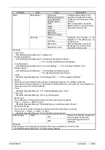
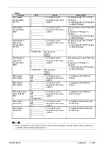
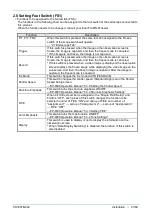
Function
Description
F/T
(Freeze / Trigger)
When this switch is pressed, the observation screen displays a frozen
image while displaying a video image on the sub-screen only during the
period of the time set in the “Freeze Time”.
When this switch is pressed again while the image is frozen, the image is
captured and then, the freeze mode is canceled.
* If the image is not frozen when this switch is pressed, the freeze mode is
canceled without capturing the image.
* The “Freeze Time” is set by service personnel.
F+T
( Trigger)
When this switch is pressed, the observation screen displays a frozen
image while displaying a video image on the sub-screen only during the
period of the time set in the “Freeze Time”.
The image is captured automatically, and then the freeze mode is
canceled. When this switch is pressed again while the image is frozen, the
freeze mode is canceled without capturing the image.
* The “Freeze Time” is set by service personnel.
FRZ (Freeze)
When this switch is pressed, the observation screen displays a frozen
image while displaying a video image on the sub-screen.
When this switch is pressed again while the image is frozen, the freeze
mode is canceled without capturing the image.
To capture it, press the switch assigned to “Trigger”.
* Even if the switch to which “Record” is assigned is pressed after pressing
the switch to which “Freeze” is assigned, the freeze mode is not
canceled.
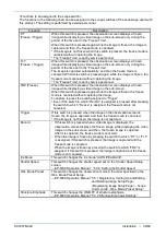
Trigger
If this switch is pressed when the image on the observation screen is
frozen, the image is captured, and then the freeze mode is canceled.
* If the image is not frozen, the image is not captured.
Record
・
If this switch is pressed when a video image is displayed, the
observation screen displays the frozen image while displaying the video
image on the sub-screen, and then, the frozen image is captured.
After it is captured, the freeze mode is canceled.
・
When the image is frozen by pressing the switch to which “F/T” or “F+T”
is assigned, if this switch is pressed, the image is captured and the
freeze mode is canceled.
When the image is frozen by pressing the switch to which “FRZ” is
assigned, if this switch is pressed, the image is captured but the freeze
mode is not canceled.
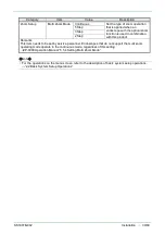
。
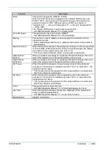
Iris Mode
This switch changes the iris mode “AUTO/PEAK/AVE”.
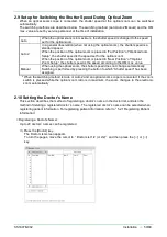
Shutter Speed
This switch changes the shutter speed set on the Shutter Speed Setup
screen.
→EP-6000 Operation Manual “5.3.6 Setting the Shutter Speed”
Obs. Mode Preset
This switch changes the observation mode in the order specified on the
Obs. Mode Preset Setup.
→EP-6000 Operation Manual “5.5.1 Registering, Calling Up and Editing
and Deleting Image Setup Page -
<Registering Image Setup Page> - Scope
Common tab - Obs. Mode Preset Setup”
Structure Emphasis
This switch changes the ON/OFF of structure emphasis.
→EP-6000 Operation Manual “5.3.2 Structure Emphasis Settings”
Summary of Contents for EP-6000
Page 1: ...Processor EP 6000 FV693A Service Manual SR1807 N002 Ver 1 Oct 2018 ...
Page 5: ...SS1807 N002 General Table of Contents 1 1 General Table of Contents ...
Page 13: ...SS1807 N002 Caution in Safety 1 12 Caution in Safety ...
Page 25: ...SS1807 N002 Product Specifications 1 11 Product Specifications ...
Page 36: ...SS1807 N002 Instruction of System 1 106 Instruction of System ...
Page 133: ...SS1807 N002 Instruction of System 98 106 ELC PCB Patient PCB APC PCB APC PCB APC PCB DC Pump ...
Page 139: ...SS1807 N002 Instruction of System 104 106 9 4 Outline of PCB roles ...
Page 142: ...SS1807 N002 Failure Analysis 1 64 Failure Analysis ...
Page 206: ...SS1807 N002 Checkup Replacement and Adjustment 1 137 Checkup Replacement and Adjustment ...
Page 343: ...SS1807 N002 Service Parts List 1 19 Service Parts List ...
Page 352: ...SS1807 N002 Service Parts List 10 19 2 2 2 4 1 3 3 2 3 3 6 5 ...
Page 356: ...SS1807 N002 Service Parts List 14 19 1 3 3 4 1 2 1 3 X 4 1 3 3 4 3 3 ...
Page 358: ...SS1807 N002 Service Parts List 16 19 3 1 2 1 ...
Page 360: ...SS1807 N002 Service Parts List 18 19 Fig 09 5 4 2 3 1 ...
Page 362: ...SS1807 N002 Periodical Maintenance 1 15 Periodical Maintenance ...
Page 377: ...SS1807 N002 Installation 1 68 Installation ...
Page 445: ...SS1807 N002 ...


