


SS1807-N002
Installation
-
48/68
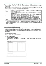
Function
Description
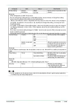
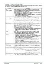
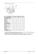
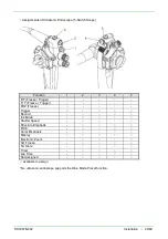
Electronic Zoom:
Zoom In
*1
This switch changes the zoom ratio of the electronic zoom. The ratio
changes each 0.05 steps from the range of x1.00 to x2.00. This switch
performs zoom-in only.
Electronic Zoom:
Zoom Out
*1
This switch changes the zoom ratio of the electronic zoom. The ratio
changes each 0.05 steps from the range of x1.00 to x2.00. This switch
performs zoom-out only.
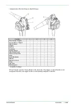
Optical Zoom:
Zoom In
When an optical zoom scope is connected, this switch changes the zoom
ratio of the optical zoom. This switch performs zoom-in only.
Optical Zoom:
Zoom Out
When an optical zoom scope is connected, this switch changes the zoom
ratio of the optical zoom. This switch performs zoom-out only.
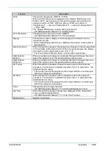
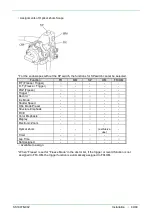
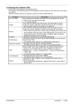
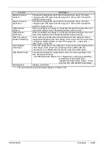
PinP Sub-screen
Position Switching
If this switch is pressed when the observation screen displays a frozen
image while displaying the video image on the sub-screen, the sub-screen
changes its display position in order of the upper left → upper right →
lower right → lower left.
Hide / Display
Subscreen
When the observation screen displays a frozen image while displaying the
video image on the sub-screen, pressing of this switch hides the
sub-screen. To re-display the sub-screen, press this switch again.
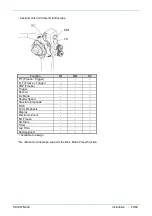
Obs. Mode Preset
This switch changes the observation mode in the order specified on the
Obs. Mode Preset Setup.
→EP-6000 Operation Manual “5.5.1 Registering, Calling Up and Editing
and Deleting Image Setup Page -
<Registering Image Setup Page> - Scope
Common tab - Obs. Mode Preset Setup”
Not Assigned
Assigns no function.
*1
:
The zoom ratio of some 530 series scopes is x1.00 to x1.95.
Summary of Contents for EP-6000
Page 1: ...Processor EP 6000 FV693A Service Manual SR1807 N002 Ver 1 Oct 2018 ...
Page 5: ...SS1807 N002 General Table of Contents 1 1 General Table of Contents ...
Page 13: ...SS1807 N002 Caution in Safety 1 12 Caution in Safety ...
Page 25: ...SS1807 N002 Product Specifications 1 11 Product Specifications ...
Page 36: ...SS1807 N002 Instruction of System 1 106 Instruction of System ...
Page 133: ...SS1807 N002 Instruction of System 98 106 ELC PCB Patient PCB APC PCB APC PCB APC PCB DC Pump ...
Page 139: ...SS1807 N002 Instruction of System 104 106 9 4 Outline of PCB roles ...
Page 142: ...SS1807 N002 Failure Analysis 1 64 Failure Analysis ...
Page 206: ...SS1807 N002 Checkup Replacement and Adjustment 1 137 Checkup Replacement and Adjustment ...
Page 343: ...SS1807 N002 Service Parts List 1 19 Service Parts List ...
Page 352: ...SS1807 N002 Service Parts List 10 19 2 2 2 4 1 3 3 2 3 3 6 5 ...
Page 356: ...SS1807 N002 Service Parts List 14 19 1 3 3 4 1 2 1 3 X 4 1 3 3 4 3 3 ...
Page 358: ...SS1807 N002 Service Parts List 16 19 3 1 2 1 ...
Page 360: ...SS1807 N002 Service Parts List 18 19 Fig 09 5 4 2 3 1 ...
Page 362: ...SS1807 N002 Periodical Maintenance 1 15 Periodical Maintenance ...
Page 377: ...SS1807 N002 Installation 1 68 Installation ...
Page 445: ...SS1807 N002 ...


