


SS1807-N002
Instruction of System
-
35/106
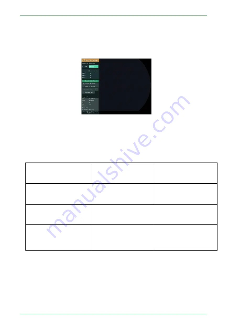
2.4.1 Scope Color
2.4.1.1 Scope Color Auto Adjust
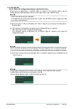
Adjusts the color of the connected Endoscope automatically. Insert the distal end of the
Endoscope into the specified integrating sphere and then perform “Scope Color Auto Adjust”.
Move the cursor to “Scope Color Auto Adjust” and then press the Enter key. The screen for
“Scope Color Auto Adjust” appears.
Adjust the color data for each Endoscope.
When this screen is displayed at the first time, data written on the EEPROM of the Endoscope is
displayed.
[Note] To write automatically adjusted values onto the EEPROM, select “Execute Writing”.
The relationship between each adjusting operation and the resulting image is shown in
the table below.
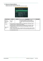
<Adjusting operations and the resulting images>
Adjusting operation
Image displayed immediately
after adjustment
Image displayed after the power
is turned off and then on (to
read deta from the EEPROM
again)
(1) “Execute Auto Adjust” is
selected.
(2) “Execute Writing” is selected.
(3) “Save and Exit” is selected.
Image after automatic
adjustment
Image after automatic
adjustment
(1) “Execute Auto Adjust” is
selected.
(2) “Execute Writing” is selected.
(3) The Esc key is pressed.
Image before automatic
adjustment
Image after automatic
adjustment
(1) “Execute Auto Adjust” is
selected.
(2) “Save and Exit” is selected
without selecting “Execute
Writing”.
Image after automatic
adjustment
Image before automatic
adjustment
Summary of Contents for EP-6000
Page 1: ...Processor EP 6000 FV693A Service Manual SR1807 N002 Ver 1 Oct 2018 ...
Page 5: ...SS1807 N002 General Table of Contents 1 1 General Table of Contents ...
Page 13: ...SS1807 N002 Caution in Safety 1 12 Caution in Safety ...
Page 25: ...SS1807 N002 Product Specifications 1 11 Product Specifications ...
Page 36: ...SS1807 N002 Instruction of System 1 106 Instruction of System ...
Page 133: ...SS1807 N002 Instruction of System 98 106 ELC PCB Patient PCB APC PCB APC PCB APC PCB DC Pump ...
Page 139: ...SS1807 N002 Instruction of System 104 106 9 4 Outline of PCB roles ...
Page 142: ...SS1807 N002 Failure Analysis 1 64 Failure Analysis ...
Page 206: ...SS1807 N002 Checkup Replacement and Adjustment 1 137 Checkup Replacement and Adjustment ...
Page 343: ...SS1807 N002 Service Parts List 1 19 Service Parts List ...
Page 352: ...SS1807 N002 Service Parts List 10 19 2 2 2 4 1 3 3 2 3 3 6 5 ...
Page 356: ...SS1807 N002 Service Parts List 14 19 1 3 3 4 1 2 1 3 X 4 1 3 3 4 3 3 ...
Page 358: ...SS1807 N002 Service Parts List 16 19 3 1 2 1 ...
Page 360: ...SS1807 N002 Service Parts List 18 19 Fig 09 5 4 2 3 1 ...
Page 362: ...SS1807 N002 Periodical Maintenance 1 15 Periodical Maintenance ...
Page 377: ...SS1807 N002 Installation 1 68 Installation ...
Page 445: ...SS1807 N002 ...


