background image

THE COMPONENTS IDENTIFIED BY THE MARK 


 ”

 ON THE SCHEMATIC

DIAGRAM AND IN THE PARTS LIST ARE CRITICAL FOR SAFETY.
PLEASE REPLACE ONLY BY THE COMPONENTS SPECIFIED ON THE SCHEMATIC
DIAGRAM AND IN THE PARTS LIST.
IF YOU USE PARTS NOT SPECIFIED, IT MAY RESULT IN A FIRE AND AN
ELECTRICAL SHOCK.

FUJI PHOTO FILM CO., LTD.

Ref.No.: ZM00576-10

2

Printed in Japan 2004.1

2

  DIGITAL CAMERA

FinePix S3Pro

US/CA/EU/EG/GE/AS/JP-Model

SERVICE MANUAL

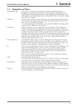
 WARNING

Summary of Contents for FinePix S3Pro

Page 1: ...SE REPLACE ONLY BY THE COMPONENTS SPECIFIED ON THE SCHEMATIC DIAGRAM AND IN THE PARTS LIST IF YOU USE PARTS NOT SPECIFIED IT MAY RESULT IN A FIRE AND AN ELECTRICAL SHOCK FUJI PHOTO FILM CO LTD Ref No ZM00576 102 Printed in Japan 2004 12 DIGITAL CAMERA FinePix S3Pro US CA EU EG GE AS JP Model SERVICE MANUAL WARNING ...

Page 2: ...ered connections Check the entire board surface for solder splasher and bridges 2 Check the interboard wiring to ensure that no wires are pinched or contact high wattage resistors 3 Look for unauthorized replacement parts particularly transistors that were installed during a previous repair Point them out to the customer and recommend their replacement 4 Look for parts which though functioning sho...

Page 3: ...soft installation 43 4 5 1 Various downloading software decompressions preservation methods and notes 43 4 5 2 Installation of DSC jig driver 44 4 5 3 Adjusting soft initiation method 44 4 6 Initial Settings of the Adjustment Software 45 4 7 Starting the Adjustment Software 48 4 8 F4 CCD Defect Correction 51 4 9 F5 CAMERA Adjustment 53 4 10 F1 Battery Voltage Adjustment 56 4 11 F11 Video Adjustmen...

Page 4: ...inuous AF servo Manual AF system TTL phase difference detection with auxiliary AF flash AF frame selection Single area AF Dynamic AF Dynamic AF Mode with Closest Subject Priority is available White balance Automatic scene recognition Preset Fine Shade Fluorescent Daylight Fluorescent Warm White Fluorescent Cool White Incandescent Custom 2 settings Self timer 20 sec 10 sec 5 sec 2 sec Flash Manual ...

Page 5: ...ssory shoe cover 1 Fitted on the camera body z Eyepiece cap 1 z LCD cover 1 Fitted on the camera body z Camera body cap 1 Fitted on the camera body z Video cable 1 approx 1 5 m 4 9ft mini plug 3 5 mm dia to pin plug cable z IEEE 1394 4 pin to 6 pin cable 1 approx 1 5 m 4 9ft z USB cable mini B 1 z Cable holder 1 z Clamp filter 1 z Synchronizing terminal cap 1 Fitted on the camera body z Remote rel...

Page 6: ...varies slightly depending on the type of subject Also the discrepancy between the actual number of available shots and the standard number grows as the capacity of the media increases For CCD RAW files is displayed as the resolution Quality Mode Image File Size DPC 16 16 MB DPC 32 32 MB DPC 64 64 MB DPC 128 128 MB FINE Number of recorded pixels 4256 2848 1440 960 3024 2016 2304 1536 DPC 256 256 MB...

Page 7: ...capable of showing all the actual colors Color Temperature Low temperature light sources such as a candle flame are strongly red while high temperature light sources such as a gas burner flame are strongly blue The color of the light for these temperatures is expressed as a color temperature K Kelvin The light of the sun at midday in a completely clear sky is taken to be 5500K EV A number that den...

Page 8: ... switch Sub command dial Depth of field check button Shutter button for vertical shooting Strap mount Flash exposure compensation button Exposure compensation button Top display panel LCD illuminator button Shutter button Release mode switch unlock button Exposure mode dial Release mode switch Synchronizing terminal cap Synchronizing terminal Lock lever for vertical shooting ...

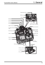
Page 9: ...on BACK button xD Picture Card slot CF Microdrive eject button CF Microdrive slot Slot cover 4 direction button AE L AF L button Metering system selector dial PLAY button FUNC button F1 button F2 button F3 button F4 button LCD monitor Rear display panel Synchro mode button Auto Exposure Bracketing button Diopter adjustment knob Rubber eyecup Viewfinder ...

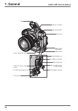
Page 10: ...switch Battery holder release catch Lens release button Strap mount Flash USB socket mini B Battery holder IEEE 1394 socket VIDEO OUT Video output socket DC IN 5V power input socket Terminal cover Digital terminal cover Remote release socket 10 pin terminal Remote release socket cap ...

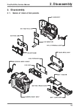
Page 11: ... 2 Disassembly 2 1 Names of internal Components SW PWB ASSY LCD MONITOR REAR FRAME RELESE HOLDER CONST 10Pin TERMINAL ASSY CCD UNIT BOTTOM FRAME ASSY CCD PWB ASSY BATT HOLDER BATT CART ASSY CAMERA BODY ASSY DOT MATRIX LCD MAIN PWB ASSY R CABI ASSY ...

Page 12: ...OVER 3 Remove the 16 screws N MS2M 1 7 x 3 0 BA 4 Remove the R CABI ASSY in the direction of the arrow 5 Remove the MAIN SW FPC from the connector SW PWB ASSY CN 102 Notes on assembling the R CABI ASSY 1 Ensure that the FPC is not inserted on an angle and that it is fully inserted before locking 2 Confirm the IEEE1394 JACK is correctly matched to the hole of R CABI ASSY 3 Ensure that there are no ...

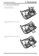
Page 13: ...rvice Manual 2 1 3 4 2 4 Removing the SW PWB ASSY 1 Remove the FPC at 3 points 2 Remove the wire harness at 1 point 3 Remove the EMI SHEET 10 FPC in the direction of the arrow 4 Remove the EMI SHEET 10 CNN in the direction of the arrow ...

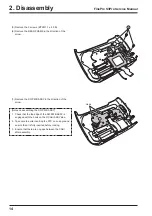
Page 14: ...7 Remove the SW PWB ASSY in the direction of the arrow Notes on assembling the SW PWB ASSY 1 Check that the top edge of the SW PWB ASSY is engaged with the hook on the R CABI ASSY side 2 Take care to avoid inserting the FPC on an angle and ensure that it is fully inserted before locking 3 Ensure that there are no gaps between the CABI after assembly ...

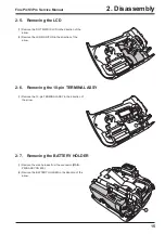
Page 15: ...f the arrow 2 Remove the LCD MONITOR in the direction of the arrow 2 6 Removing the 10 pin TERMINAL ASSY 1 Remove the 10 pin TERMINAL ASSY in the direction of the arrow 2 7 Removing the BATTERY HOLDER 1 Remove the wire harness from the connector MAIN PWB ASSY CN 600 2 Remove the BATTERY HOLDER in the direction of the arrow ...

Page 16: ...BODY from the connector MAIN PWB ASSY CN 700 5 Remove the MAIN CCD FPC from the connector MAIN PWB ASSY CN 100 6 Remove the wire harness CAMERA BODY from the connector MAIN PWB ASSY CN 104 7 Remove the FPC CAMERA BODY from the connector MAIN PWB ASSY CN 103 8 Remove the 6 screws MS2M 1 7 x 3 0 N 9 Remove the MAIN PWB ASSY in the direction of the arrow Notes on assembling the MAIN PWB ASSY Check th...

Page 17: ...rvice Manual 1 4 3 2 2 9 Removing the CCD PWB ASSY and CCD UNIT 1 Remove the SHIELD SHEET 2 Remove the 3 screws CCD PWB SCREW 3 Remove the EMI SHEET L in the direction of the arrow 4 Remove the EMI SHEET R in the direction of the arrow ...

Page 18: ... S3Pro Service Manual 6 5 8 7 5 Remove the solder on the CCD PWB ASSY 36 locations 6 Remove the CCD PWB ASSY in the direction of the arrow 7 Remove the 4 screws M 1 2 x 2 4 C 8 Remove the CCD UNIT in the direction of the arrow ...

Page 19: ... screw 4 Remove A M CHANGE LEVER 5 Remove two screws 6 Remove two screws 7 Remove four screws 8 Remove FRONT COVER BLACK in the direction of the arrow 9 Remove FRONT CABINET UNIT in the direction of the arrow 10 Remove four screws 11 Remove the MAIN FRAME 1 2 3 8 11 7 9 6 4 5 10 10 7 13 13 13 13 15 Black 12 14 Step 2 12 Do the lens cap 13 Remove five screws 14 Float TOP COVER UNIT in the direction...

Page 20: ... TOP COVER UNIT to the grip side As for the grip side the harness is stopped with solder Step 4 17 Peel off the insulation tape then discharge the MAIN CONDENSER before remove the wiring harnesses 18 Remove six harness and remove TOP COVER UNIT completely Notes of assembly of TOP COVER UNIT Hang part A inner EYE PIECE BARREL UNIT And build in TOP COVER UNIT Revised 1 Dec 2004 ...

Page 21: ...CASE UNIT Remove in the order indicated by circled numbers Step 1 1 Remove two screws 2 Remove the hook in two places Step 2 3 Remove two screws 4 Float TOP COVER FPC Step 3 5 Pull out the harness of the flash in the direction of the arrow after floating TOP COVER FPC Revised 1 Dec 2004 ...

Page 22: ...Disassembly FinePix S3Pro Service Manual Step 4 6 Remove FLASH UP SPRING in the direction of A 7 Remove one screws 6 7 A 8 Step 5 8 Remove SB LOWER CASE UNIT in the direction of the arrow Revised 1 Dec 2004 ...

Page 23: ...his model These innovations are described below 1 Large format 15 5 x 23 0 mm Super CCD Honeycom SRII featuring a new structural design Ultra high image quality with a maximum recorded image size of 4256 x 2848 pixels 12 1 megapixels provided by the Honeycom Signal Processing System and a resolution of 12 34 effective megapixels high sensitivity S pixels 6 17 million R pixels designed to increase ...

Page 24: ...by the AUTO computing unit and then sent to the CAM BLOCK ACS IC906 so that the optimal AE AWB and AF values are obtained Recording onto the xD Pictuer Card Microdrive The image data stored in the SDRAM IC101 IC102 IC103 and IC106 is sent one line at a time to the signal processor IC IC104 UCS2 CSP via the I O bus in the signal processor IC In the signal processor the data is unpacked and the foll...

Page 25: ... 9 4 X T F I G U B E D e r o C U P C k 6 1 e h c a c I t n o C S U B C M A R D S C A M D Peripheral BUS 96MHz O I S T D W T F M U C I C A D T R O P C K L C l a n r e t n I M A R D e A l a n r e t n I B M A R D e r e f f u B O I G E P J A o i d u D A A o i d u l u i r e S N E G C D C N E C D F T I D E M A O R P C Y F I D C C A O T U C C E R A D LCD Driver CMX4006T IC500 D C L C P F A R E M A C F I ...

Page 26: ...GND LCDDAT 4 6 40 LCDDAT 4 GND 41 17 GND LCDDAT 3 5 41 LCDDAT 3 GND 42 16 GND LCDDAT 2 4 42 LCDDAT 2 COM 24 GND 43 15 GND LCDDAT 1 3 43 LCDDAT 1 CS 23 CCD_4 7V 44 14 CCD_4 7V LCDDAT 0 2 44 LCDDAT 0 VST 22 CCD_4 7V 45 13 CCD_4 7V LCDCLK 1 45 LCDCLK VCK 21 CCD_4 7V 46 12 CCD_4 7V CN102 CN1002 EN 20 CCD_4 7V 47 11 CCD_4 7V FH26 45S 0 3SHW FH26 45S 0 3SHW DWN 19 GND 48 10 GND VDD 18 CCD_ 9V 49 9 CCD_ ...

Page 27: ...27 3 Schematics FinePix S3Pro Service Manual 3 6 Circuit Diagrams 3 6 1 CCD BLOCK ...

Page 28: ...28 3 Schematics FinePix S3Pro Service Manual 3 6 2 DCDC BLOCK ...

Page 29: ...29 3 Schematics FinePix S3Pro Service Manual 3 6 3 IEEE1394 BLOCK ...

Page 30: ...30 3 Schematics FinePix S3Pro Service Manual 3 6 4 PROCESS BLOCK ...

Page 31: ...31 3 Schematics FinePix S3Pro Service Manual 3 6 5 CARD BLOCK 3 6 6 DCDC BLOCK CAMERA BODY ...

Page 32: ...32 3 Schematics FinePix S3Pro Service Manual 3 6 7 PARTNER CHIP BLOCK ...

Page 33: ...33 3 Schematics FinePix S3Pro Service Manual 3 6 8 PWON BLOCK ...

Page 34: ...34 3 Schematics FinePix S3Pro Service Manual 3 6 9 USB2 0 BLOCK ...

Page 35: ...35 3 Schematics FinePix S3Pro Service Manual 3 6 10 LCD BLOCK ...

Page 36: ...36 3 Schematics FinePix S3Pro Service Manual 3 6 11 SW BLOCK ...

Page 37: ...37 3 Schematics FinePix S3Pro Service Manual 3 7 Mounted Parts Diagrams 3 7 1 CCD PWB ASSY SIDE A SIDE B ...

Page 38: ...38 3 Schematics FinePix S3Pro Service Manual 3 7 2 MAIN PWB ASSY SIDE A ...

Page 39: ...39 3 Schematics FinePix S3Pro Service Manual SIDE B ...

Page 40: ...40 3 Schematics FinePix S3Pro Service Manual 3 7 3 SW PWB ASSY SIDE A SIDE B ...

Page 41: ...spection AF inspection Common with the FinePix S2 Pro ZJ00611 100 X Y stage for AF adjustment AF inspection Common with the FinePix S2 Pro ZJ00863 100 S3Pro Battery jig Battery adjustment Common with the FinePix S2 Pro FZ03284 100 Video cable VIDEO adjustment Common with the FinePixA310 ZJ00650 100 VIDEO adjustment jig Video adjustment Common with the FinePixA310 FZ03983 100 AC Cable For EG Use wi...

Page 42: ...ra must be removed from the inspection interchangeable lens to prevent it from switching its aperture automatically and thus modify the lens so it can be used for adjustment The modification procedure is shown below Step 1 Turn the focus ring 1 so that the interchangeable lens s distance scale reads 0 45 then place the lens upside down Step 2 Cut the stopper for the camera using side cutters etc S...

Page 43: ...ment software are in a specified Web server and both of these are the compression of ZIP form files Therefore after downloading these compression files from the Web server the decompression of the file is necessary In the decompression software if the decompression of the ZIP form can be done any software is OK Please prepare each one for the decompression software The decompression and the preser...

Page 44: ...adjustment software can not start when foldername is changed 4 5 2 Installation of DSC jig driver Since this camera uses the USB for communications with the personal computer in order to start the PC adjustment software the DSC jig driver needs to be installed in the personal computer beforehand The DSC jig driver is the same as that for the FinePix S7000 so if this jig driver software is already ...

Page 45: ...f If the program is rewritten the adjustment software will not startup Step 1 Double click on the FFW exe execute file of the adjustment software to open the FFW Startup screen Fig 4 6 1 Step 2 Click on Settings 1 in Fig 4 6 2 in the menubar of the startup window Then select Mode setting 2 in Fig 4 6 2 from the pull down menu that appears Fig 4 6 2 1 2 FinePix S3Pro_W Adjustment Software Start up ...

Page 46: ... check Step 5 Select the Hardware tab 1 in Fig 4 6 5 in the Customize dialog box that appears Input the values for PI O port and P Board 2 in Fig 4 6 5 PIO 0 10 12 14 16 PIO 1 11 13 15 17 Set the Hardware items 3 in Fig 4 6 5 as follows Item Details Debug Mode Select Default Step 6 Once the above settings have been made click on Apply 4 in Fig 4 6 5 in the Customize dialog box to complete setup Th...

Page 47: ...for Auto Adjust in user program Help Help Basic software help FF help User program help Focus Not used with this adjustment software Version Version information for basic software Table FFW exe Commands Cautions When Adjusting 1 FinePix S3Pro cannot adjust the EVR data reading and writing Details are right tables 2 End Setting returns the camera from the Jig mode to the Product Mode End Setting is...

Page 48: ...adjustment software 4 Proceed with adjustment after reading the cautions here and the relevant cautions noted in the Service Manual Press the Enter key to proceed to the Jig Mode Setup screen Fig 4 7 2 FinePix S3Pro_W Adjustment Software Start up Screen Select Start from Operate on the FFW Toolbar The adjustment software starts Fig 4 7 2 4 7 Starting the Adjustment Software Step 1 Double click on ...

Page 49: ...nnect the USB cable to the camera 8 Supply 6 00 volts to the camera from the S3Pro battery jig 9 Switch ON the camera power while pressing the shutter button for vertical shooting 10 Check that the shutter speed is displays on the LCD of the camera body Press the Enter key after completing the procedure of 1 10 Fig 4 7 3 FirmWare 1 00 Vendor Name FUJIFILM Manufacturer FUJIFILM ProductName FinePix ...

Page 50: ...ersion number of the adjustment software 2 After running firmware download other adjustments may be required depending on the content of the download software In such cases the items to be adjusted and the sequence of adjustment will be indicated separately 3 After starting the adjustment software and beginning communication with the camera always run End Setting following adjustment and before re...

Page 51: ...s settings so that file extensions are displayed 2 In addition to numbers letters are also used in the CCD serial No The data file name is instructed in the same manner in this case 3 Ensure that the CCD serial No is read correctly If the file name is read incorrectly CCD data for another camera will be loaded when this file is used Step 2 Download the ZIP file of top four digits from Web server h...

Page 52: ...en completed correctly The CCD Defect Correction Complete screen appears Step 3 CCD Defect Correction is completed Press the Enter key to return to the Adjustment Item Selection Screen Fig 4 8 3 CCD Defect correction Preparations 1 Enter the 8 digit ccdserial number in the CCD number input dialog box The file extrension dat need not be entered 2 Insert the floppy disk in the A drive floppy disk dr...

Page 53: ...with the instructions on the screen Note An error will occur during CAMERA adjustment and adjustment cannot be completed unless the pattern box is calibrated correctly The Camera adjustment with filter screen appears CAMERA Adjustment CAMERA Adjustment Preparations 1 Prepare the LB140 filter 2 Adjust the color temperature of the pattern box PTB450 to 6100 50K 3 Adjust the luminance of the pattern ...

Page 54: ...r CAMERA Adjustment Fig 4 9 3 Camera adjustment with filter 1 Set the distance between the camera and pattern box 2 Place the LB140 filter in front of the lens When preparations are complete press the Enter key LB140 filter 20mm or 20mm or less less Center Center Pattern box PTB450 CAMERA Setup for CAMERA Adjustment Fig 4 9 2 Step 3 The Camera adjustment without filter screen appears Step 4 Write ...

Page 55: ...55 4 Adjustments FinePix S3Pro Service Manual Camera adjustment is completed Press the Enter key to return to the Adjustment Item Selection Screen Fig 4 9 4 Step 5 ...

Page 56: ...t the stabilized power supply to ensure that the voltage is not reduced excessively from the measured point The adjustment software may produce an error if communication between the adjustment software and the camera is disrupted Restart the adjustment software in this case Step 1 Select F1 Battery Voltage Adjustment on the Adjustment Items Select screen The Battery Voltage Adjustment Preparation ...

Page 57: ...t the S3Pro BATT jig and the camera are connected If not return to the Jig Mode Setup screen and connect the S3Pro BATT jig and the camera 2 Supply power 6 0V to the camera from the S3Pro BATT jig When preparations are complete press the Enter key on the PC Fig 4 10 1 Step 2 Run the adjustment in accordance with the instructions on the screen The 4 56V Input screen appears Step 3 The 4 40V Input s...

Page 58: ...3 Supply 6 00V 0 05V When preparation is complete press the Enter key Fig 4 10 3 Battery Voltage Adjustment 1 Supply 4 56V 0 02V 0 00V When preparation is complete press the Enter key Result 4C 2 Supply 4 40V 0 02V 0 00V When preparation is complete press the Enter key Step 4 The 6 00V Input screen appears Step 5 Write the adjustment data to the Flash ROM when adjustment has been completed correct...

Page 59: ...59 4 Adjustments FinePix S3Pro Service Manual Fig 4 10 5 The BATTERY adjustment is completed Press the Enter key to return to the Adjustment Item selection Screen Step 6 ...

Page 60: ...stment jig 2 If the waveform of the brightness signal Y or color signal C does not appear in the WAVE No 0 window during adjustments check the connections of the video adjustment jig Step 1 Select F11 Video Adjustment on the Adjustment Items Select screen The Video Adjustment Preparation screen appears Step 2 Run the adjustment in accordance with the instructions on the screen Write the adjustment...

Page 61: ...ro Service Manual Fig 4 11 3 Step 3 Video adjustment is completed 1 Disconnect Video cable from camera 2 Close the WaAVE No 0 window by close button Press the Enter key to return to the Adjustment Item selection Screen Fig 4 11 2 ...

Page 62: ...r LCD Panel 1 Adjust the display using the up and down arrow keys on your computer until the pattern is most clearly visible Write the adjustment data to the Flash ROM when adjustment has been completed correctly The Rear LCD Panel Adjustment Complete screen appears REAR LCD PANEL Adjustment Press UP Arrow and DOWN Arrow of the arrow key to PC as the quadrangle painted out is most clearly displaye...

Page 63: ... setting no cross talk shadowing appears in the areas adjacent to the black sections A and B and the black sections appear completely black Step 3 Area A Area B Sample of the Rear LCD Panel adjustment pattern REAR LCD PANEL adjustment is completed Press the Enter key to return to the Adjustment Item selection Screen Fig 4 12 2 ...

Page 64: ...oad of the firmware is needed FUJI SERVICE BULLETIN is contacted from FTYO QA Till then disregard this item Setup for Firmware Download Step 1 Select F8 Firmware Download on the Adjustment Items Select screen The Firmware Download Start screen appears USB cable PC for adjustments and checks AC 5VX ...

Page 65: ...eed is displays on the LCD of the camera body The system returns to the Jig Mode Setup screen when press the Enter key Fig 4 13 2 Firmware Download LED lights to orange while downloading the firmware Do not turn off the power while downloading the firmware c FinePixS3Pro_W Firmwear SU500 bin Press the ENTER Key to start download Fig 4 13 1 Step 2 Run the adjustment in accordance with the instructi...

Page 66: ...FinePix S3Pro be unique throughout the world For this reason each device has a unique ID as determined by the USB standard If multiple devices with the same USB_ID are connected to a single PC the PC will be unable to identify each USB device thus preventing operation Item Details Repair Date Date information is acquired from the PC and written Administrator ID C 43 Repair Station U S 61 a SAPPORO...

Page 67: ...write IEEE1394_ID write and product mode settings Mass Storage recognition Press the Enter key Fig 4 14 1 Step 1 Select F12 End Setting on the Adjustment Items Select screen The End Setting Description screen appears Step 2 Run the adjustment in accordance with the instructions on the screen The IEEE1394_ID screen appears ...

Page 68: ...31234 Once you have entered the number click the OK button or press the Enter key on your computer 31234 Fig 4 14 2 10001 99999 Step 3 Enter a 5 digit serial number in the serial number input dialog box as directed by the instructions in the Enter IEEE_ID serial number window Example of serial number and value generation Enter a number made up of the second digit in the camera s serial number foll...

Page 69: ...s the Enter key Fig 4 14 4 USB_ID writing Repair site ID input menu The repair site is selected from an undermentioned list A SAPPORO SS M BRITAIN B SENDAI SS N GERMANY C TOKYO SS O FRANCE D NAGOYA SS P SPAIN E OSAKA SS Q ITALY F HIROSHIMA SS R NETHERLANDS G FUKUOKA SS S BELGIUM H USA T SWEDEN I CANADA U SWITZERLAND J HAWAII V NORWAY K TAIWAN W FINLAND X SINGAPORE L CHINA Z OTHERS Fig 4 14 5 Step ...

Page 70: ...y returns to the Jig Mode Setup Screen after pressing the Enter key on the computer End on the adjustment software menu bar in the Jig Mode Setup Screen to terminate the adjustment software Fig 4 14 7 FinePix S3Pro Adjustment completed 1 Remove USB cable from the camera 2 Press the Enter key The adjustment software returns to the Jig mode setup screen after press the Enter key ...

Page 71: ...valent Ammeter For general use able to measure up to 1mA Replacement Lens for Inspection Common with adjustment jig ZJ00396 100 Power cable jig Common with adjustment jig ZJ00213 100 Grey chart Common with adjustment jig ZJ00254 100 LB140 filter Common with adjustment jig ZJ00006 100 High resolution chart Common with FinePixS1Pro FinePix4700Z ZJ00398 100 Wired remote controller Commacial item Niko...

Page 72: ...Set to ISO sensitivity 200 4 Set aperture to F5 6 5 Set number of recorded pixels to 6M STD others to defaults 6 Set as for flash adjustment 7 Take photograph Adjustment and measurement method No significant dents in body Click sound of all switches and operation of sliders normal No significant foreign matter or cloudiness in viewfinder Flash mechanism opens and closes smoothly 2 5 00 0 5V 5 Conf...

Page 73: ...n the flash hot shoe GND contact The resistance value at this time should be inf Pop down the flash and take a photograph 3 Take photograph 1 Turn on the Power_on of the main body 2 Open and tighten the slot cover 1 Place the xD picture card which contains the photograph recorded in STEP4 and 5 in image check camera 2 The PLAY button is pushed 3 Playback flash check photographic image 4 Playback E...

Page 74: ... 03V little by little PRE_END voltage 4 Lower the voltage to 4 32V 0 03V little by little END voltage 1 Switch power OFF Adjustment and measurement method 1 6 00V 0 1V 2 Playback screen disappears 3 Thing that FORMAT OK is displayed 4 Thing that NO IMAGES is displayed in LCD monitor 1 The test image is played by the LCD monitor 2 Thing of 1 A or less current 3 Thing that battery PRE END display ap...

Page 75: ...attern 6 ISO sensitivity 200 7 Diopter adjustment knob bottom 8 Power switch Turning off 9 4 direction switch Lock 10 Inspection battery inspection SSFDC not in camera 11 No contamination on LCD Optical finder 12 Clean exterior of camera 13 Upgrade packaging in accordance with parts list details Adjustment and measurement method 2 The camera may be set to the mode set at shipment from the factory ...

Page 76: ...t the focusing mode to M 7 Execute the LIVE IMAGE ON And adjust the position of the camera so that the chart displayed in the LCD monitor may become the same angle as Fig 5 4 2 Step 4 After you have completed the settings in steps 1 to 3 above Execute LIVE IMAGE ON and execute ENLARGE Adjust a focus ring so that a chart looks sharp and press the shutter button taking care to avoid any camera shake...

Page 77: ...age Fig 5 4 2 3 The peripherally enlarged image is normal if a resolution of 1000 lines can be confirmed Check location Service resolution value Center horizontal vertical 1200 Peripheral horizontal vertical 1000 Note The resolution values given in this description are not the original FinePix S3Pro resolution values TV resolution The values given are according to the high resolution chart set in ...

Page 78: ...era Step 4 Set the camera s exposure mode dial to M Step 5 Hold down the release mode switch lock release button and set the release mode switch to S1 Frame Step 6 Hold down the Synchro mode and Illuminator buttons and switch the camera on Step 7 When you press the shutter button the mirror stays up and the shutter stays open Step 8 Hold the camera so that light shines on the CCD OLPF and check fo...

Page 79: ...election tool for the enlarged CCD dusting check image Fig 5 5 5 is useful for checking individual pixels Step 5 If the dusting is 12 pixels or larger it can be regarded as CCD OLPF dusting and the CCD should be cleaned again At shipment from the factory soiling smaller than 12 pixels is regarded as OK Note In a normal environment there will be considerable dusting of the CCD OLPF surface Conseque...

Page 80: ...the camera stand for the AF Solid chart and set the X Y stage for AF adjustment on the base plate Step 2 Mount the camera on the X Y stage for AF adjustment Step 3 Remove the hexagonal bolt in the top of the AF solid chart block and remove the upper level solid chart Step 4 Align the AF intermediate chart surface horizontally and vertically with the 0 Emarkings on the lower level and upper level s...

Page 81: ...e camera is now ready to shoot Step 3 Manually set the focusing ring on the checking lens to the nearest distance and push the Shutter button of the camera A preview image is displayed and then transferred to the specified folder Step 4 Repeat step 3 three times 3 near focus shots are saved Step 5 Manually set the focusing ring on the checking lens to INF the furthest distance and push the Shutter...

Page 82: ...dly grouped into 3 categories as outlined below 1 Problems attributable to how the camera is used Resolution setting Can be resolved by selecting a high quality mode 12M JPEG Fine RAW in the resolution settings Sharpness setting Check the resolution problems in SOFT mode Diffraction when shots are taken using an excessively small aperture 1 Check the F stop setting and try taking the shot with an ...

Page 83: ...S N A110 FZ04797 100 IEEE1394 CABLE N A111 FZ03284 100 VIDEO CABLE N A112 FZ00363 200 CLAMP FILTER N A113 BB18148 100 CABLE HOLDER N A114 FZ04809 100 EYEPIECE COVER N A115 FZ05352 600 CD ROM N A116 FZ06103 100 EMI FILTER N A117 BB18002 100 CERTIFICATION SEAL N A118 BB18385 100 DEST LBL 5000US J FG N A119 BL00372 100 IMPORTANT SAFETY N A120 BL00373 100 US WARRANTY N A A A111 A109 A105 A113 A114 A11...

Page 84: ...394 CABLE N A111 FZ03284 100 VIDEO CABLE N A112 FZ00363 200 CLAMP FILTER N A113 BB18148 100 CABLE HOLDER N A114 FZ04809 100 EYEPIECE COVER N A115 FZ05352 600 CD ROM N A116 FZ06103 100 EMI FILTER N A117 BB18002 100 CERTIFICATION SEAL N A118 BB18385 400 DEST LBL 5000CA J FG N A119 BL00430 201 OWNER S MANUAL S3PRO ENG N A120 BL00430 301 OWNER S MANUAL S3PRO FRG N A A A111 A109 A105 A113 A114 A116 A12...

Page 85: ...Z04809 100 EYEPIECE COVER N A115 FZ05352 600 CD ROM N A116 FZ06103 100 EMI FILTER N A117 BB18002 100 CERTIFICATION SEAL N A118 BB18385 200 DEST LBL 5000EU J FG N A119 FZ05210 300 AC POWERCORD E AC 5VW E N A120 BL00430 201 OWNER S MANUAL S3PRO ENG N A A A111 A109 A119 A105 A113 A114 A116 A128 A125 A124 A126 A120 A127 A121 A122 A123 A115 A104 A117 A103 A118 A101 A102 A108 A106 A107 A110 A129 A130 A1...

Page 86: ...A110 FZ04797 100 IEEE1394 CABLE N A111 FZ03284 100 VIDEO CABLE N A112 FZ00363 200 CLAMP FILTER N A113 BB18148 100 CABLE HOLDER N A114 FZ04809 100 EYEPIECE COVER N A115 FZ05352 600 CD ROM N A116 FZ06103 100 EMI FILTER N A117 BB18002 100 CERTIFICATION SEAL N A118 BB18385 300 DEST LBL 5000EG J FG N A119 FZ05210 400 AC POWERCORD EG AC 5VW EG N A120 BL00176 100 WARRANTY CARD EG N A A A111 A110 A109 A10...

Page 87: ...65 100 USB HARNESS N A110 FZ04797 100 IEEE1394 CABLE N A111 FZ03284 100 VIDEO CABLE N A112 FZ00363 200 CLAMP FILTER N A113 BB18148 100 CABLE HOLDER N A114 FZ04809 100 EYEPIECE COVER N A115 FZ05352 600 CD ROM N A116 FZ06103 100 EMI FILTER N A117 BB18002 100 CERTIFICATION SEAL N A118 BB18385 500 DEST LBL 5000GE J FG N A119 FZ05210 300 AC POWERCORD E AC 5VW E N A120 BL00430 401 OWNER S MANUAL S3PRO G...

Page 88: ...65 100 USB HARNESS N A110 FZ04797 100 IEEE1394 CABLE N A111 FZ03284 100 VIDEO CABLE N A112 FZ00363 200 CLAMP FILTER N A113 BB18148 100 CABLE HOLDER N A114 FZ04809 100 EYEPIECE COVER N A115 FZ05352 600 CD ROM N A116 FZ06103 100 EMI FILTER N A117 BB18002 100 CERTIFICATION SEAL N A118 BB18385 600 DEST LBL 5000AS J FG N A119 FZ05210 300 AC POWERCORD E AC 5VW E N A120 BL00430 201 OWNER S MANUAL S3PRO E...

Page 89: ...040 100 NI NH BATTERY JN HR AA JN BK 4S E A109 FZ05241 100 USB CABLE N A110 FZ04797 100 IEEE1394 CABLE N A111 FZ03284 100 VIDEO CABLE N A112 FZ00363 200 CLAMP FILTER N A113 BB18148 100 CABLE HOLDER N A114 FZ04809 100 EYEPIECE COVER N A115 FZ05352 600 CD ROM N A116 FZ06103 100 EMI FILTER N A117 BB12944 100 WARRANTY CARD N A118 BL00190 100 SAFETY CARD N A119 BL00430 101 OWNER S MANUAL S3PRO JPN N A1...

Page 90: ...nePix S3pro onto the spool position Notes After the repair job for Camera Body Assy is finished please peel off the above label and put it together with DSC block After that adjust it like when you do after replacing Camera Body Assy Ref No Parts No Description Remarks A201 ZPK0102 100 Packing box for S3Pro CAMERA BODY With inside frame A202 ZPK0103 100 Protector for S3Pro CAMERA BODY One pair in ...

Page 91: ... No Description Comment EL 6 3 CAMERA BODY M201 FZ06022 100 CAMERA BODY ASSY M202 BB17618 100 TERMINAL COVER N M203 FZ04876 100 SHOECAP N M204 FZ04801 100 RUBBER EYECUP N M205 BB17663 100 BODY CAP N M206 FZ04807 100 SYNCHRO CAP N M201 M203 M204 M206 M205 M202 ...

Page 92: ...100 BACK BUTTON N M310 BB17640 100 CHANGE BUTTON N M311 BB17641 100 FUNC BUTTON N M312 BB17642 100 PLAY BUTTON N M313 BB17643 100 RUBBER KEY F N M314 BB17644 100 RUBBER KEY C N M315 BB17645 100 CARD COVER N M316 BB17646 100 CARD RUBBER N M317 BB17650 100 CARD KONB N M318 BB18005 100 CSP CARD N M319 BB18000 100 CARD LOCK N M320 BB17651 100 CARD PLATE N M321 BB17649 100 LABEL CARD N M322 BB17335 100...

Page 93: ...SY N M409 BF05083 100 RELEASE HOLDER CONST N M410 BB17335 400 SCREW BT2M1 7X4 0B N M411 BF05370 100 CCD UNIT M412 CB1469 A102 CCD PWB ASSY M413 BB11386 100 SCREW_M1 2X2 4C N M414 BB18126 100 CCD PWB SCREW N M415 FZ06093 100 SHIELD SHEET M416 FZ06036 100 MAIN CCD FPC N M417 BF05086 100 10PIN TERMINAL ASSY N M418 BB18524 100 EMI SHEET 10CNN N M419 BB17336 200 SCREW N MS2M1 7X3 0BA N M420 BB17657 100...

Page 94: ...416 FZ06036 100 MAIN CCD FPC N M417 BF05086 100 10PIN TERMINAL ASSY N M418 BB18524 100 EMI SHEET 10CNN N M419 BB17336 200 SCREW N MS2M1 7X3 0BA N M420 BB17657 100 DIGITAL TERMINAL COVER N E D G F F E D G A A H K I J B C C I J K H B M403 M406 M405 M407 M408 M413 M431 M414 M430 M412 M416 M411 M432 M410 M418 M428 M427 M425 M424 M429 M403 M404 M426 M402 M419 M419 M421 M419 M420 M422 M419 M417 M419 M42...

Page 95: ...BF05083 100 RELEASE HOLDER CONST N M410 BB17335 400 SCREW BT2M1 7X4 0B N M411 BF05370 100 CCD UNIT M412 CB1469 A102 CCD PWB ASSY M413 BB11386 100 SCREW_M1 2X2 4C N M414 BB18126 100 CCD PWB SCREW N M415 FZ06093 100 SHIELD SHEET M416 FZ06036 100 MAIN CCD FPC N M417 BF05086 100 10PIN TERMINAL ASSY N M418 BB18524 100 EMI SHEET 10CNN N M419 BB17336 200 SCREW N MS2M1 7X3 0BA N M420 BB17657 100 DIGITAL T...

Page 96: ...R CASE UNIT N N902 1C998 038 SB UP SWITCH UNIT N N903 1C998 040 SHOE MOLD UNIT N N904 1C998 042 EXTERNAL LCD WINDOW UNIT N N905 1C998 689 TOP COVER UNIT N N906 1K001 077 SCREW N N907 1K010 469 SCREW N N S N S SPONGE N N S N S SPONGE N N910 1K119 308 RUBBER SEAL N N911 1K230 548 FLASH UP SPRING N N912 1K240 867 SHOE SPRING N N913 1K406 032 1 SHOE N N914 1K611 833 LUG PLATE A N N915 1K631 102 SB CAS...

Page 97: ...N F N N1011 1K119 213 EXPOSURE PREVENT SPONGE N N1012 1K119 214 SPONGE N N1013 1K119 237 ADHESIVE DOUBLE COATED TAPE N N S N S TAPE N N1015 1K119 329 1 TAPE N N S N S ADHESIVE DOUBLE COATED TAPE N N1017 1K206 171 POWER DIAL N N1018 1K208 242 EXPOSURE COMPENSATION BUTTON N N1019 1K208 243 COMPENSATION BUTTON N N1020 1K208 244 ILLUMINATION ON OFF BUTTON N N1021 1K208 245 2 RELEASE BUTTON N N1022 1K2...

Page 98: ... BALL N N1108 1K119 318 DROP PROOF SPONGE N N1109 1K119 327 DROP PROOF SPONGE N N1110 1K201 143 METERING MODE DIAL N N1111 1K208 246 AE LOCK BUTTON N N1112 1K208 247 REWIND SIDE PUSH BUTTON CAP A N N1113 1K208 248 REWIND SIDE PUSH BUTTON CAP B N N1114 1K208 249 WINDING LOCK MOLD N N1115 1K220 496 SPRING N N1116 1K220 532 MODE DIAL CLICK SPRING N N1117 1K220 548 SB LOCK LEVER SPRING N N1118 1K241 3...

Page 99: ... 463 SCREW N N1208 1K010 464 SCREW N N1209 1K010 648 SCREW N N1210 1K010 483 SCREW N N1211 1K010 259 SCREW N N1212 H1 17060FA SCREW N N1213 1K087 632 MODEL BADGE N N1214 1K087 633 CCD BADGE N N1215 1K103 739 SHEET F1 N N1216 1K119 201 A M COVER PLATE N N1217 1K119 326 DROP PROOF SPONGE N N S N S TAPE N N1219 1K206 170 A M CHANGE LEVER N N1220 1K208 240 PREVIEW BUTTON N N1221 1K208 241 FLASH UP BUT...

Page 100: ...NECTOR CN100 FGB145 0571 CONNECTOR CJ 57P FN 0 3MM NH N CN101 FGB144 0061 CONNECTOR CJ 6P FN 0 5MM NH N CN102 FGB145 0451 CONNECTOR CJ 45P FN 0 3MM NH N CN103 FGB106 0121 CONNECTOR CJ 12P FN 0 5MM NH N CN104 FGA113 0021 CONNECTOR CJ 2P RN 1 5MM PH N CN300 FZ05869 100 JACK IEEE1394 N CN400 FZ05744 100 JACK USB MINI B N CN500 FGB144 0241 CONNECTOR CJ 24P FN 0 5MM NH N CN501 FGA155 0021 CONNECTOR CJ ...

Page 101: ... issued that cover this device Technical Update No Date Title Details Other Revised pages Matter of service Page 19 to 22 2004 051 1 Dec 2004 How to remove exterior parts of camera body manual revision Page 96 to 99 Part lists of exterior parts of camera body Matter of service Revised pages 2004 057 27 Dec 2004 Page 81 AF testing procedure correction manual revision Page 96 to 99 Parts list correc...

Page 102: ...26 30 Nishiazabu 2 chome Minato ku Tokyo 106 8620 Japan FUJI PHOTO FILM CO LTD ...

Reviews: