70
4. Adjustments
FinePix S3Pro Service Manual
USB_ID writing
Selected USA.
Press the [Enter] key!
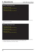
<Fig. 4-14-6>
<Step 7>
—> The [FinePix S3Pro Adjustment End] screen appears.
<Step 8>
--> The display returns to the [Jig Mode Setup Screen] after pressing the [Enter] key on the computer.
--> End on the adjustment software menu bar in the [Jig Mode Setup Screen] to terminate the adjustment software.
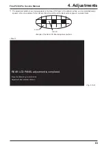
<Fig. 4-14-7>
FinePix S3Pro Adjustment completed.
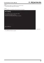
1)Remove USB cable from the camera.
2)Press the [Enter] key.
--> The adjustment software returns to the Jig mode setup screen
after press the [Enter] key.
Summary of Contents for FinePix S3Pro
Page 27: ...27 3 Schematics FinePix S3Pro Service Manual 3 6 Circuit Diagrams 3 6 1 CCD BLOCK ...
Page 28: ...28 3 Schematics FinePix S3Pro Service Manual 3 6 2 DCDC BLOCK ...
Page 29: ...29 3 Schematics FinePix S3Pro Service Manual 3 6 3 IEEE1394 BLOCK ...
Page 30: ...30 3 Schematics FinePix S3Pro Service Manual 3 6 4 PROCESS BLOCK ...
Page 31: ...31 3 Schematics FinePix S3Pro Service Manual 3 6 5 CARD BLOCK 3 6 6 DCDC BLOCK CAMERA BODY ...
Page 32: ...32 3 Schematics FinePix S3Pro Service Manual 3 6 7 PARTNER CHIP BLOCK ...
Page 33: ...33 3 Schematics FinePix S3Pro Service Manual 3 6 8 PWON BLOCK ...
Page 34: ...34 3 Schematics FinePix S3Pro Service Manual 3 6 9 USB2 0 BLOCK ...
Page 35: ...35 3 Schematics FinePix S3Pro Service Manual 3 6 10 LCD BLOCK ...
Page 36: ...36 3 Schematics FinePix S3Pro Service Manual 3 6 11 SW BLOCK ...
Page 38: ...38 3 Schematics FinePix S3Pro Service Manual 3 7 2 MAIN PWB ASSY SIDE A ...
Page 39: ...39 3 Schematics FinePix S3Pro Service Manual SIDE B ...
Page 40: ...40 3 Schematics FinePix S3Pro Service Manual 3 7 3 SW PWB ASSY SIDE A SIDE B ...
Page 102: ...26 30 Nishiazabu 2 chome Minato ku Tokyo 106 8620 Japan FUJI PHOTO FILM CO LTD ...


