40
4. Adjustments
FinePix S5000 Service Manual
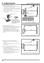
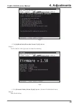
<Step 1>
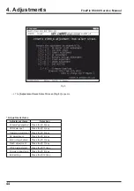
Double-click on the [FFW.exe] file (Fig.E) in the
adjustment software folder to display the [FFW
Start-up Screen] (Fig.F).
<Step 2>
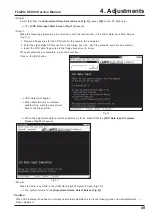
Click on [Setting] (Fig.G-1) on the [menu bar] on the
screen.
Select [Mode setting] (Fig.G-2) from the pull-down
menu.
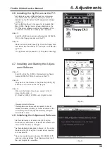
<Step 3>
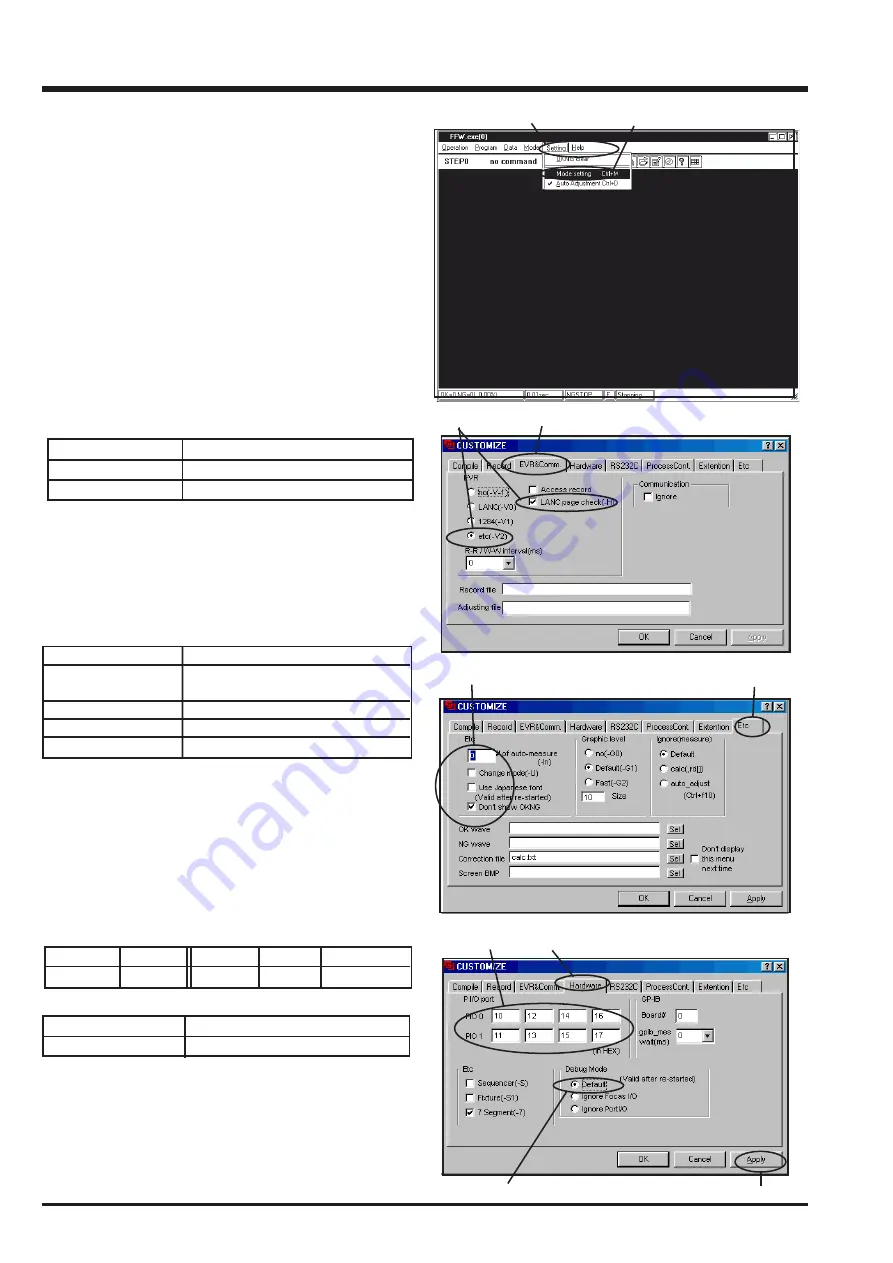
Select the [EVR&Comm.] menu on the [Mode
setting] dialog screen (Fig.H-1).
Set the [EVR] items as follows (Fig.H-2).
Item
Details
etc(-V2)
Check
LANC Page
Check
<Fig.G>
1
2
<Fig.H>
<Fig.I>
<Fig.J>
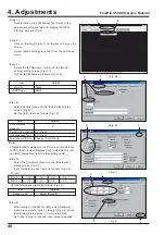
<Step 4>
Select the [Etc] menu on the [Customize] dialog
screen (Fig.I-1).
Set the [Etc] items as follows (Fig.I-2).
Item
Details
# of automatic
measure
0
Permit mode change Do't check
Use Japanese font
Do't check
Don't show OK NG
Check or Don't check
(Note)
If [Disable OKNG display] on the PC screen (Fig.H) is set
to OFF, the PC screen displays [OK] if adjustment is OK,
and [NG] if adjustment is NG (either setting is OK).
<Step 5>
Select the [Hardware] menu on the [Customize]
dialog screen (Fig.J-1).
Input the data to each items as follows (Fig.J-2).
PI /port
PIO 0
10
12
14
16
PIO 1
11
13
15
17
Set the [Hardware] items as follows (Fig.J-3).
Item
Details
Debug mode
Select [Default]
<Step 6>
When setup on the [EVR], [Etc], and [Hardware]
menus is complete, click on [Apply] (Fig.J-4) on the
[Customize] dialog screen to complete setup.
No further setup is required once setup is applied.
2
1
1
1
2
2
4
3
Summary of Contents for FinePix S5000
Page 20: ...20 3 Schematics FinePix S5000 Service Manual 3 6 CCD BLOCK Schematic Diagram ...
Page 21: ...21 FinePix S5000 Service Manual 3 Schematics 3 7 CAMERA BLOCK Schematic Diagram ...
Page 22: ...22 FinePix S5000 Service Manual 3 Schematics 3 8 PROCESS BLOCK Schematic Diagram ...
Page 23: ...23 3 Schematics FinePix S5000 Service Manual 3 9 POWER BLOCK Schematic Diagram ...
Page 24: ...24 3 Schematics FinePix S5000 Service Manual 3 10 LCD EVF BLOCK Schematic Diagram ...
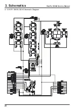
Page 26: ...26 3 Schematics FinePix S5000 Service Manual 3 13 KEY SW BLOCK Schematic Diagram ...
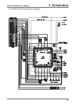
Page 27: ...27 3 Schematics FinePix S5000 Service Manual 3 14 MOTOR BLOCK Schematic Diagram ...
Page 28: ...28 3 Schematics FinePix S5000 Service Manual 3 15 POWER ON BLOCK Schematic Diagram ...
Page 29: ...29 3 Schematics FinePix S5000 Service Manual 3 16 FLASH BLOCK Schematic Diagram ...
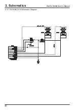
Page 30: ...30 3 Schematics FinePix S5000 Service Manual 3 17 R SW BLOCK Schematic Diagram ...
Page 82: ...26 30 Nishiazabu 2 chome Minato ku Tokyo 106 8620 Japan FUJI PHOTO FILM CO LTD ...

