49
4. Adjustments
FinePix S5000 Service Manual
<Step 6>
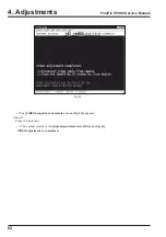
Select [F4] from the
[Adjustment Items Select Screen (Fig.5)].
(press
[F4]
on the PC keyboard)
---> The
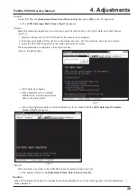
[CCD Data Input Start Screen (Fig.11)]
appears.
<Step 7>
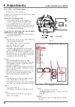
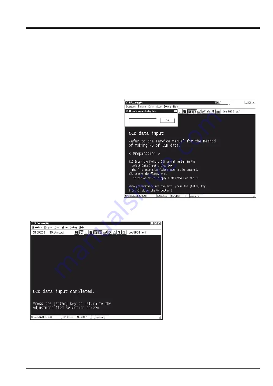
Make the following preparations in accordance with the instructions on the [CCD Data input Start Screen
(Fig.11)].
1 Prepare a floppy disk for the CCD data for the camera to be adjusted.
2 Enter the eight-digits CCD serial No. in the dialog box (the ‘.dat’ file extension need not be entered).
3 Insert the CCD data floppy disk in the floppy disk drive (A: drive).
When preparations are complete, press the Enter key.
Click on the [OK] button.
---> CCD Data input begins.
---> When adjustment is completed
satisfactorily, write the adjustment
data to the Flash_ROM.
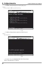
---> When the adjustment data is written satisfactorily to the Flash ROM the
[CCD Data Input Complete
Screen (Fig.12)]
appears.
<Step 8>
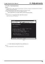
Press the Enter key while in the [CCD Data input Complete Screen (Fig.12)].
---> The system returns to the
[Adjustment Items Select Screen (Fig.5)].
Caution:
When CCD data input has been run, always ensure that adjustment is run in the following order. Camera adjustment --->
Flash adjustment.
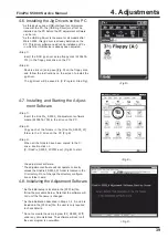
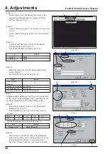
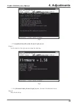
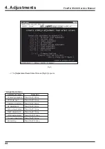
Fig.11
Fig.12
Summary of Contents for FinePix S5000
Page 20: ...20 3 Schematics FinePix S5000 Service Manual 3 6 CCD BLOCK Schematic Diagram ...
Page 21: ...21 FinePix S5000 Service Manual 3 Schematics 3 7 CAMERA BLOCK Schematic Diagram ...
Page 22: ...22 FinePix S5000 Service Manual 3 Schematics 3 8 PROCESS BLOCK Schematic Diagram ...
Page 23: ...23 3 Schematics FinePix S5000 Service Manual 3 9 POWER BLOCK Schematic Diagram ...
Page 24: ...24 3 Schematics FinePix S5000 Service Manual 3 10 LCD EVF BLOCK Schematic Diagram ...
Page 26: ...26 3 Schematics FinePix S5000 Service Manual 3 13 KEY SW BLOCK Schematic Diagram ...
Page 27: ...27 3 Schematics FinePix S5000 Service Manual 3 14 MOTOR BLOCK Schematic Diagram ...
Page 28: ...28 3 Schematics FinePix S5000 Service Manual 3 15 POWER ON BLOCK Schematic Diagram ...
Page 29: ...29 3 Schematics FinePix S5000 Service Manual 3 16 FLASH BLOCK Schematic Diagram ...
Page 30: ...30 3 Schematics FinePix S5000 Service Manual 3 17 R SW BLOCK Schematic Diagram ...
Page 82: ...26 30 Nishiazabu 2 chome Minato ku Tokyo 106 8620 Japan FUJI PHOTO FILM CO LTD ...

