68
4. Adjustments
FinePix S5000 Service Manual
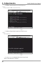
---> The
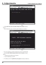
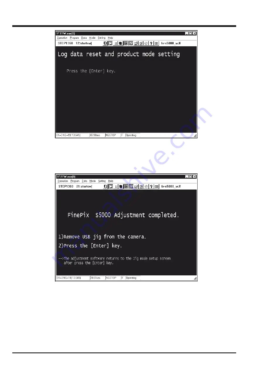
[Log data reset and Product Mode Setting Screen (Fig.42)]
is appears.
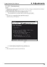
<Step 6>
Press the [Enter] key while in the [Product Mode Setting Screen (Fig.42)].
---> When the settings are completed normally they are saved to the flash ROM,
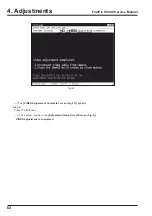
and the
[FinePix S5000 Adjustment finished Screen (Fig.43)]
is appears.
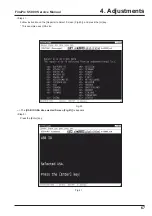
<Step 8>
1. Remove jig and all cables from the camera.
2. Press the [Enter] key on the PC.
---> The display returns to the
[Inithal Screen (Fig.2)]
after pressing the [Enter] key.
Fig.42
Fig.43
Summary of Contents for FinePix S5000
Page 20: ...20 3 Schematics FinePix S5000 Service Manual 3 6 CCD BLOCK Schematic Diagram ...
Page 21: ...21 FinePix S5000 Service Manual 3 Schematics 3 7 CAMERA BLOCK Schematic Diagram ...
Page 22: ...22 FinePix S5000 Service Manual 3 Schematics 3 8 PROCESS BLOCK Schematic Diagram ...
Page 23: ...23 3 Schematics FinePix S5000 Service Manual 3 9 POWER BLOCK Schematic Diagram ...
Page 24: ...24 3 Schematics FinePix S5000 Service Manual 3 10 LCD EVF BLOCK Schematic Diagram ...
Page 26: ...26 3 Schematics FinePix S5000 Service Manual 3 13 KEY SW BLOCK Schematic Diagram ...
Page 27: ...27 3 Schematics FinePix S5000 Service Manual 3 14 MOTOR BLOCK Schematic Diagram ...
Page 28: ...28 3 Schematics FinePix S5000 Service Manual 3 15 POWER ON BLOCK Schematic Diagram ...
Page 29: ...29 3 Schematics FinePix S5000 Service Manual 3 16 FLASH BLOCK Schematic Diagram ...
Page 30: ...30 3 Schematics FinePix S5000 Service Manual 3 17 R SW BLOCK Schematic Diagram ...
Page 82: ...26 30 Nishiazabu 2 chome Minato ku Tokyo 106 8620 Japan FUJI PHOTO FILM CO LTD ...


