5. Inspection
69
FinePix S5000 Service Manual
5. Inspection
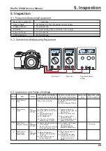
5-1. Required Measuring Equipment
5-3. Inspection and Factory Settings
5-2. Connection of Measuring Equipment
Measuring equipment
Remarks
Power supply
AC adapter (AC-5V), Regurated power supply
Digital voltmeter
For general use
Ammeter
For general use (able to measure 1mA or less)
power cable jig
For general use
xD-Picture card
For general use
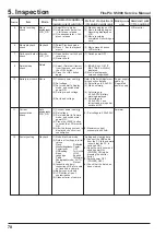
Sequemnce
Item
Mode
Preparations for adjustment
(measurement points, subject, other)
Method of adjustment
(VRs, waveforms, required values)
Measuring
equipment
and jigs
Measurement points
(VRs, positions)
1
2
3
4
Check appear-
ance
Power supply
switch
Check Movie
mode shock noise
Check macro
photography
Check focus
Visual check of camera
(1) Place battery in camera.
(2) Insert card and close card
cover.
(3) Set mode dial to still
photography mode.
(4) Turn power ON.
(5) If the date set message
appears, press Cancel.
(1) Apply an appropriate shock
to the camera.
*
Do not apply shock directly
to the lens or card cover.
(1) Macro photography
distance (approximately
10~80cm).
(2) Press shutter button to
take photographs.
No problem with click action
of switches.
No dust or fogging of finder.
(1) Applied voltage:4 AA
batteries or equivalent jig
may be used.
(2) Recording check card.
(4) Power supply LED is
green and beeps.
(5) Live image screen and text
display in LCD monitor.
(1) No problem with display
on LCD monitor.
Restoration possible
despite disruption of sync.
(1) Macro icon appears in
LCD monitor.
(2) LED beside viewfinder
changes from green to
orange (recording) to
green.
Auto
photography
LCD_ON
Auto
photography
LCD_ON
Auto
photography
LCD_ON
LCD monitor
Ammeter
Regurated power
supply
Volt meter
Summary of Contents for FinePix S5000
Page 20: ...20 3 Schematics FinePix S5000 Service Manual 3 6 CCD BLOCK Schematic Diagram ...
Page 21: ...21 FinePix S5000 Service Manual 3 Schematics 3 7 CAMERA BLOCK Schematic Diagram ...
Page 22: ...22 FinePix S5000 Service Manual 3 Schematics 3 8 PROCESS BLOCK Schematic Diagram ...
Page 23: ...23 3 Schematics FinePix S5000 Service Manual 3 9 POWER BLOCK Schematic Diagram ...
Page 24: ...24 3 Schematics FinePix S5000 Service Manual 3 10 LCD EVF BLOCK Schematic Diagram ...
Page 26: ...26 3 Schematics FinePix S5000 Service Manual 3 13 KEY SW BLOCK Schematic Diagram ...
Page 27: ...27 3 Schematics FinePix S5000 Service Manual 3 14 MOTOR BLOCK Schematic Diagram ...
Page 28: ...28 3 Schematics FinePix S5000 Service Manual 3 15 POWER ON BLOCK Schematic Diagram ...
Page 29: ...29 3 Schematics FinePix S5000 Service Manual 3 16 FLASH BLOCK Schematic Diagram ...
Page 30: ...30 3 Schematics FinePix S5000 Service Manual 3 17 R SW BLOCK Schematic Diagram ...
Page 82: ...26 30 Nishiazabu 2 chome Minato ku Tokyo 106 8620 Japan FUJI PHOTO FILM CO LTD ...


