FinePix S5800/S800 Service Manual
3
Confidential: FUJIFILM Service Center Use Only
RoHS lead-free compliance
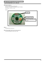
Because this product is RoHS lead-free compliant, use the designated after-sales parts and the designated lead-free solder
when performing repairs.
<Background & Overview>
With the exception of parts and materials expressly excluded from the RoHS directive
(*1)
, all the internal connections and
component parts and materials used in this product are lead-free compliant
(*2)
under the European RoHS directive.
*1: Excluded items (list of the main lead-related items)
• Lead included in glass used in fluorescent tubes, electronic components and cathode-ray tubes
• Lead in high-melting-point solder (i.e. tin-lead solder alloys that contain 85% lead or more)
• Lead in ceramic electronic parts (piezo-electronic devices)
• Mercury contained in fluorescent tubes is also excluded.
*2: Definition of lead-free
A lead content ratio of 0.1 wt% or less in the applicable locations (solder, terminals, electronic components, etc.)
<Reference>
RoHS:
The name of a directive issued by the European Parliament aimed at restricting the use of
certain designated hazardous substances included in electrical and electronic equipment.
Designated substances (6): Lead, mercury, cadmium, hexavalent chromium, polybrominated biphenyls (PBBs) and
polybrominated diphenyl ether (PBDE)
<Lead-free soldering>
When carrying out repairs, use a designated lead-free solder, bearing in mind the differing work practices for conventional
solder (eutectic) and lead-free solder.
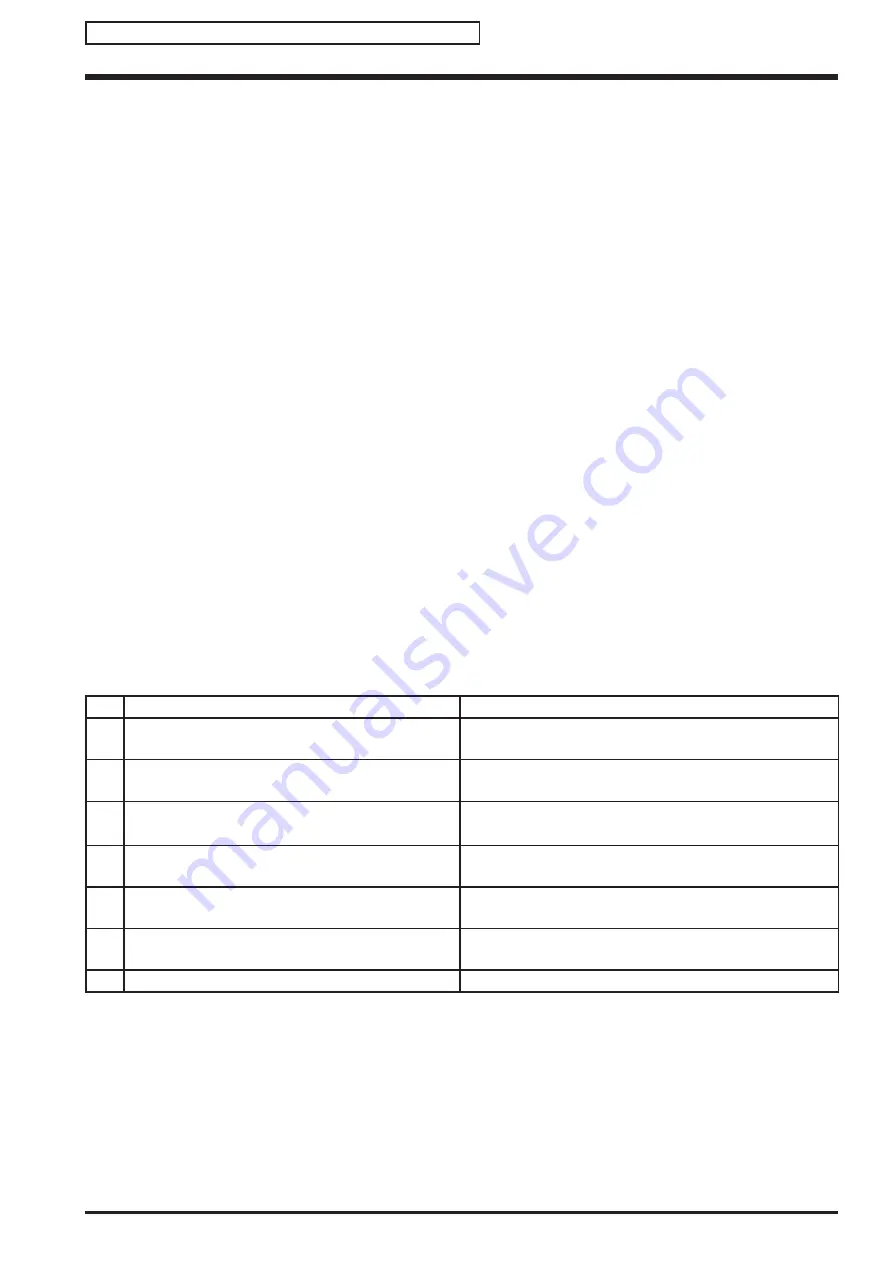
Differences in the soldering work for lead-free and eutectic solder
When the soldering work practices for eutectic solder and lead-free solder are compared, the main differences are as
shown below. In particular, when lead-free solder is used, the solder tends to be less workable than when eutectic solder is
used. Accordingly, the soldering techniques used must take that into account.
Difference
Countermeasure
1
The solder starts melting later.
The initial melting point of lead-free solder is high, so you
have to get used to it.
2
Poor wetting
Move the tip of the soldering iron around to heat the entire
connection to the melting temperature and assist wetting.
3
Solder feed rate is difficult to control.
Use the solder (wire) diameter and soldering iron that are
best suited to connection being soldered.
4
Wetting the insides of through holes is especially
difficult.
First apply solder to the area immediately around the
through hold and then feed the solder into the hole.
5
During repairs (or modifications) removing solder
from inside through holes is difficult.
Use a suitable wicking wire (with a suitable method and
heating) and a suction tool.
6
There is serious carbonization of the soldering iron.
Either put solder onto the soldering iron tip after completing
the work, or turn the iron off frequently.
7
The surface is not glossy.
Learn to recognize the appearance of the surface.


